


Hi all,
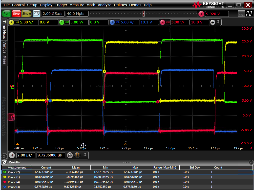
I have been working on getting a closed loop phase shift converter up and running and I am 95% of the way to having things working. Unfortunately I'm seeing some glitches that are causing big problems. Essentially what I'm trying to do is have a slow start algorithm run while I monitor the output voltage of my converter. That process works, however when I switch over from the soft start routine to the normal phase shift operation I get glitches on the "slave" phase shifted ePWM modules. The problem I am seeing is that the period on those particular channels is too long for several switching cycles. I am not using the stock PSFB code; I actually ended up putting in a phase offset in the ePWM1A/B channels and inverting the ePWM2A/B channels to get the proper phase shift I was looking for. I'm not sure if this might be a source of the issue I am seeing. As can be seen below the ePWM1A/B signals (red and blue) have the proper period as soon as the ePWM modules turn on. The ePWM2A/B signals (yellow and green) however have much longer periods than programmed. To avoid glitches I even turned the ePWM modules into input GPIO pins temporarily and only turn them back to ePWM modules as the last step of setup. Provided below are the start up routine and the code for the PSFB setup, as well as a scope capture. I'm running out of ideas and don't have a solid idea of what the source of the problem might be. Any help would be appreciated. - Lance
//Open Loop Start Up and Initialization Code
#if (INCR_BUILD == 1) 	// Closed loop PSFB PWM Driver
//----------------------------------------------------------------------
   	//Initialize settings for slowstart and reference point for the 2P2Z controller block
	float Vref = 0.8;
   	float slowstartscale = 0.98;
   	int ADCCount12bit = 4096;


   	// Configure ADC to be triggered from EPWM1 Period event
   	//Map channel to ADC Pin
   	ChSel[0]=1;		//Map channel 0 to pin ADC-A1
   	// for additional ADC conversions modify below
   	ChSel[1]=1;		//An
   	/*ChSel[2]=n;			//An
   	ChSel[3]=n;			//An
   	ChSel[4]=n;			//An
   	ChSel[5]=n;			//An
   	ChSel[6]=n;			//An
   	ChSel[7]=n;			//An
   	ChSel[8]=n;			//An
   	ChSel[9]=n;			//An
   	ChSel[10]=n;		//An
   	ChSel[11]=n;		//An
   	ChSel[12]=n;		//An
   	ChSel[13]=n;		//An
   	ChSel[14]=n;		//An
   	ChSel[15]=n;		//An
   	*/

   	// Select Trigger Event for ADC conversion
   	TrigSel[0]= ADCTRIG_EPWM1_SOCA;
   	// associate the appropriate peripheral trigger to the ADC channel
   	TrigSel[1]= ADCTRIG_EPWM1_SOCA;
   	/*TrigSel[2]= ADCTRIG_EPWMn_SOCA;
   	TrigSel[3]= ADCTRIG_EPWMn_SOCA;
   	TrigSel[4]= ADCTRIG_EPWMn_SOCA;
   	TrigSel[5]= ADCTRIG_EPWMn_SOCA;
   	TrigSel[6]= ADCTRIG_EPWMn_SOCA;
   	TrigSel[7]= ADCTRIG_EPWMn_SOCA;
   	TrigSel[8]= ADCTRIG_EPWMn_SOCA;
   	TrigSel[9]= ADCTRIG_EPWMn_SOCA;
   	TrigSel[10]= ADCTRIG_EPWMn_SOCA;
   	TrigSel[11]= ADCTRIG_EPWMn_SOCA;
   	TrigSel[12]= ADCTRIG_EPWMn_SOCA;
   	TrigSel[13]= ADCTRIG_EPWMn_SOCA;
   	TrigSel[14]= ADCTRIG_EPWMn_SOCA;
   	TrigSel[15]= ADCTRIG_EPWMn_SOCA;*/


   	// Configure the ADC with auto interrupt clear mode
   	// ADC interrupt after EOC of channel 0
   	// Configure ADC to go to continuous acquisition mode
   	ADC_SOC_CNF(ChSel,TrigSel,ACQPS,0,1);
   	EALLOW;
   	AdcRegs.ADCSOCFRC1.bit.SOC0 = 1;
   	EDIS;

   	//Slow start PWM code
   	DAB_STARTUP_PWM_CNF(2,600);

   	//Insert loop to compare Vfdbk (0-4095) to a threshold; only allow the code to progress if the threshold has been met.
	int Threshold = (int)(Vref*slowstartscale*ADCCount12bit);
	volatile Uint16 Vmon = AdcResult.ADCRESULT0;

	while (Vmon < Threshold){
	   	EALLOW;
	   	AdcRegs.ADCSOCFRC1.bit.SOC0 = 1;
	   	EDIS;

	   	Vmon = AdcResult.ADCRESULT0;
	}

   	//Access protected GPIO Control Registers to temporarily set ePWM channels to inputs to stop all switching to avoid glitches.
   	EALLOW;
	GpioCtrlRegs.GPAMUX1.bit.GPIO0 = 0;
   	GpioCtrlRegs.GPADIR.bit.GPIO0 = 0;
	GpioCtrlRegs.GPAMUX1.bit.GPIO1 = 0;
   	GpioCtrlRegs.GPADIR.bit.GPIO1 = 0;
	GpioCtrlRegs.GPAMUX1.bit.GPIO2 = 0;
   	GpioCtrlRegs.GPADIR.bit.GPIO2 = 0;
	GpioCtrlRegs.GPAMUX1.bit.GPIO3 = 0;
   	GpioCtrlRegs.GPADIR.bit.GPIO3 = 0;
   	AdcRegs.ADCSOCFRC1.bit.SOC0 = 0;
   	EDIS;


	//Reconfigure ADC to go to start-stop acquisition mode for normal closed loop operation
	ADC_SOC_CNF(ChSel,TrigSel,ACQPS,0,0);

	// Configure the EPWM1 to issue the SOC
	EPwm1Regs.ETSEL.bit.SOCAEN 	= 1;
	EPwm1Regs.ETSEL.bit.SOCASEL = ET_CTR_ZERO;	// Use ZERO event as trigger for ADC SOC
    EPwm1Regs.ETPS.bit.SOCAPRD 	= ET_1ST;        // Generate pulse on every event

	//Configure PWMDRV_PSFB Block PWM1 for 100kHz, @60MHz
	PWM_PSFB_VMC_SR_CNF(1,600,0,0);

	//Re-enable the ePWM modules (Note: May need to un-comment the GPADIR lines of code for proper operation)
   	EALLOW;
	//GpioCtrlRegs.GPAMUX1.bit.GPIO0 = 1;
   	//GpioCtrlRegs.GPADIR.bit.GPIO0 = 1;
	//GpioCtrlRegs.GPAMUX1.bit.GPIO1 = 1;
   	//GpioCtrlRegs.GPADIR.bit.GPIO1 = 1;
	//GpioCtrlRegs.GPAMUX1.bit.GPIO2 = 1;
   	//GpioCtrlRegs.GPADIR.bit.GPIO2 = 1;
	//GpioCtrlRegs.GPAMUX1.bit.GPIO3 = 1;
   	//GpioCtrlRegs.GPADIR.bit.GPIO3 = 1;
   	EDIS;

	// Digital Power CLA(DP) library initialization
	//DPL_CLAInit();
	DPL_Init();


	//ADC Block Connections
	ADCDRV_1ch_Rlt1=&Fdbk;

	//Initialize ADC Values
	Fdbk=_IQ24(0.0);

	// Initialize the controller net variables
	CNTL_2P2Z_Fdbk1 = &Fdbk;
	CNTL_2P2Z_Out1 = &Phase1;
	CNTL_2P2Z_Ref1 = &Ref;
	CNTL_2P2Z_Coef1 = &CNTL_2P2Z_CoefStruct1.b2;

	// Initialize the controller coefficients (From spreadsheet)
    CNTL_2P2Z_CoefStruct1.b2 = _IQ26(-1.697668);
    CNTL_2P2Z_CoefStruct1.b1 = _IQ26(0.07190554);
    CNTL_2P2Z_CoefStruct1.b0 = _IQ26(1.7695738);
    CNTL_2P2Z_CoefStruct1.a2 = _IQ26(-0.514138);
    CNTL_2P2Z_CoefStruct1.a1 = _IQ26(1.514138);
    CNTL_2P2Z_CoefStruct1.max = _IQ24(0.65);
    CNTL_2P2Z_CoefStruct1.min = _IQ24(0.35);

	//Initialize the net Variables/nodes
	Fdbk=_IQ24(0.25);
	Phase1=_IQ24(0.25);
	Ref=_IQ24(Vref);

	//PSFB block connections
	PWMDRV_PSFB_Phase1 = &Phase1;
	PWMDRV_PSFB_DbAtoP1 = &DbLeft;
	PWMDRV_PSFB_DbPtoA1 = &DbRight;

	//Initialize PSFB net variables
	Phase1=_IQ24(0.25);
	DbLeft=10;
	DbRight=10;


	//CLA_Init();

#endif

//PSFB Configuration Code

void PWM_PSFB_VMC_SR_CNF(int16 n, int16 period, int16 SR_Enable, int16 Comp1_Prot)
{
// n = the ePWM module number, i.e. selects the target module for init.
// ePWM(n) init.  Note EPWM(n) is the Master
    (*ePWM[n]).TBCTL.bit.PRDLD = TB_IMMEDIATE;            // set Immediate load
    (*ePWM[n]).TBPRD = period;
    (*ePWM[n]).CMPA.half.CMPA = period/4;
    (*ePWM[n]).CMPB = (period + period + period)/4;            // Fix duty at 50%
    (*ePWM[n]).TBPHS.half.TBPHS = 0;
    (*ePWM[n]).TBCTR = 0;

    (*ePWM[n]).TBCTL.bit.CTRMODE = TB_COUNT_UP;
    (*ePWM[n]).TBCTL.bit.PHSEN = TB_DISABLE;
    (*ePWM[n]).TBCTL.bit.SYNCOSEL = TB_CTR_ZERO;         //used to sync EPWM(n+1) "down-stream"
    (*ePWM[n]).TBCTL.bit.HSPCLKDIV = TB_DIV1;
    (*ePWM[n]).TBCTL.bit.CLKDIV = TB_DIV1;

    (*ePWM[n]).AQCTLA.bit.CAU = AQ_SET;
    (*ePWM[n]).AQCTLA.bit.CBU = AQ_CLEAR;

    (*ePWM[n]).DBCTL.bit.OUT_MODE = DB_FULL_ENABLE;
    (*ePWM[n]).DBCTL.bit.POLSEL = DB_ACTV_HIC;            // Active Hi Complimentary
    (*ePWM[n]).DBRED = 20;                                // dummy value for now
    (*ePWM[n]).DBFED = 20;                                // dummy value for now

// ePWM(n+1) init.  EPWM(n+1) is a slave

    (*ePWM[n+1]).TBCTL.bit.PRDLD = TB_IMMEDIATE;        // set Immediate load
    (*ePWM[n+1]).TBPRD = (period-1);
    (*ePWM[n+1]).CMPA.half.CMPA = period/2;                // Fix duty at 50%
//    (*ePWM[n+1]).CMPB = (3*period)/4;                    // Fix duty at 50%
    (*ePWM[n+1]).TBPHS.half.TBPHS = period/4;                     // zero phase shift initially
    (*ePWM[n+1]).TBCTR = 0;

    (*ePWM[n+1]).TBCTL.bit.CTRMODE = TB_COUNT_UP;
    (*ePWM[n+1]).TBCTL.bit.PHSEN = TB_ENABLE;
    (*ePWM[n+1]).TBCTL.bit.SYNCOSEL = TB_SYNC_IN;         // Sync "flow through" mode
    (*ePWM[n+1]).TBCTL.bit.HSPCLKDIV = TB_DIV1;
    (*ePWM[n+1]).TBCTL.bit.CLKDIV = TB_DIV1;

    (*ePWM[n+1]).AQCTLA.bit.ZRO = AQ_CLEAR;
    (*ePWM[n+1]).AQCTLA.bit.CAU = AQ_SET;


    (*ePWM[n+1]).DBCTL.bit.OUT_MODE = DB_FULL_ENABLE;
    (*ePWM[n+1]).DBCTL.bit.POLSEL = DB_ACTV_HIC;        // Active Hi Complimentary
    (*ePWM[n+1]).DBRED = 20;                            // dummy value for now
    (*ePWM[n+1]).DBFED = 20;                            // dummy value for now
