This thread has been locked.

If you have a related question, please click the "Ask a related question" button in the top right corner. The newly created question will be automatically linked to this question.

I've got a problem with Estimator (FAST) in Motorware!

Other Parts Discussed in Thread: MOTORWARE

Dear all,

I am trying to run sensorless vector control using the FAST Estimator in Motorware. But the problem is I got the wrong estimated result (for example: speed, overOverDcBus, angle_pu, etc) when calling the EST_run() in the main_ISR. I developed my project based on lab11,11a,11b.

	// run the estimator
    EST_run(estHandle,
            &Iab_fb_pu,
            &Vab_fb_pu,
            gAdcData.dcBus,
            gMotorVars.SpeedRef_pu);

    // get 1/Vdc to verify the operation of the Estimator
    gOneOverDcBus_est_pu = EST_getOneOverDcBus_pu(estHandle);

    // generate the motor electrical angle by estimator
    gAngle_est_pu = EST_getAngle_pu(estHandle);
    gSpeed_est_pu = EST_getFm_pu(estHandle);

    // get Idq from estimator to avoid sin and cos
    EST_getIdq_pu(estHandle,&gIdq_pu);

Although I checked the result of measurement of the motor voltage and motor current, and debugged them by PWMDAC. the result is good, as following:

a) Iab_fb_pu.value[0] and Iab_fb_pu.value[1]:

b) Vab_fb_pu.value[0] and Vab_fb_pu.value[1]:

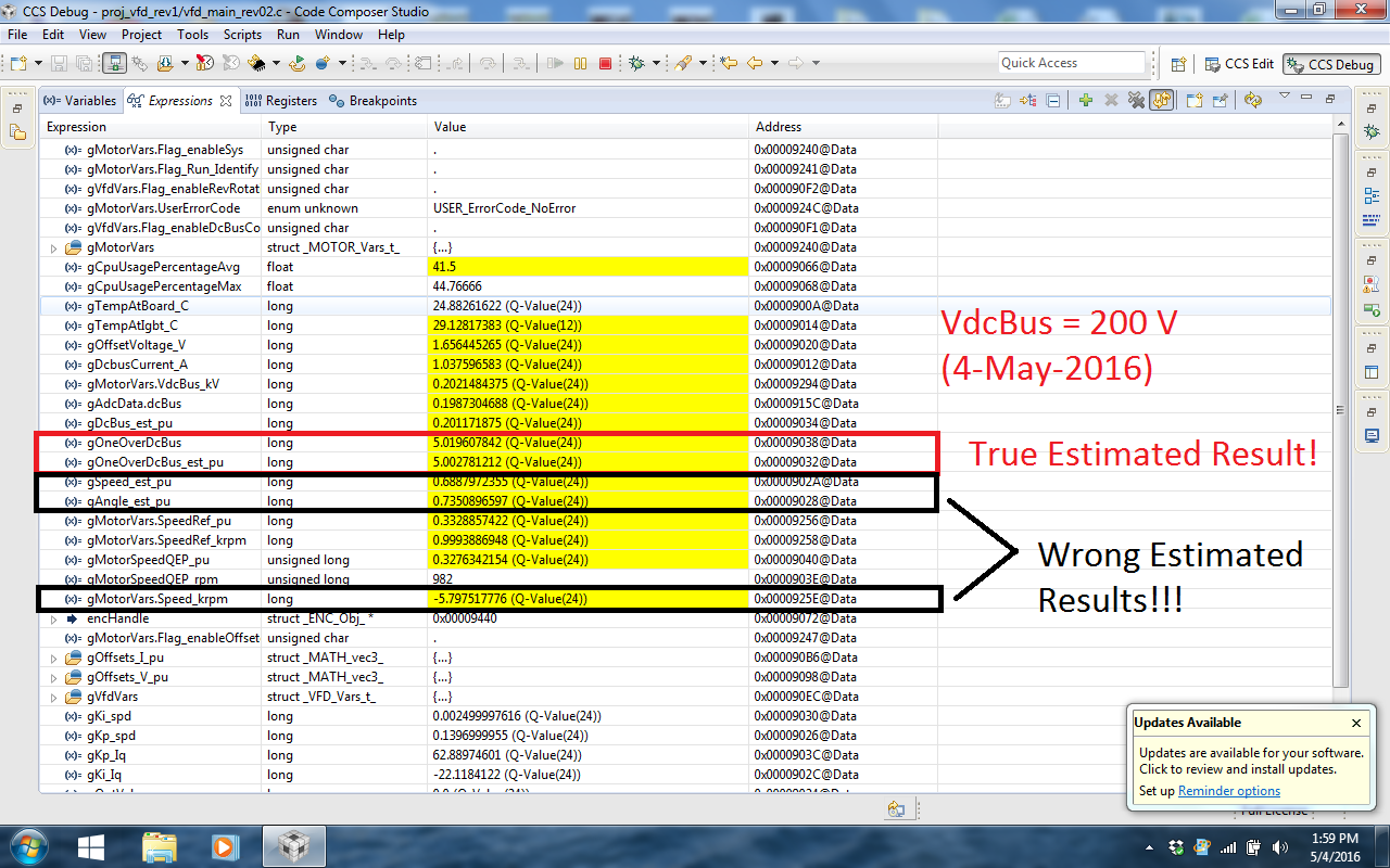
And this is the screen shot of debugging window when I run the motor to check Estimator's operation:

I don't know the reason why the Estimator did not work well. Please give me an advice.

Many thanks

  • your I_pu [2] is wildly incorrect.
    are you using your own HW? with 2 or 3 currents being measured?

    I'd also check your voltage circuits and make sure the settings and pole are in user.h correctly
  • Dear Chris,

    The result of I_pu.value[2] that you saw don't have any value, because I only used two sensors for measuring current, and the result of I_alpha & I_beta is still good with two current channels as I posted above.

    For the voltage circuit, I also checked the results which is read from ADC and put them out to PWMDAC to observe and this is the signal of V_alpha & V_beta (after removing the offset). I think there is no abnormal thing here.

    Finally, below is my setting in user.h for current and voltage channels, beside I also attach the Motorware_selecting_user_variables.xlsx so that you can verify my settings:

    motorware_selecting_user_variables.xlsx

    #define USER_IQ_FULL_SCALE_FREQ_Hz        (100.0)   // 120 Example with buffer for 4-poles 1.5 KRPM motor to be run to 3 KRPM with field weakening;
    
    #define USER_IQ_FULL_SCALE_VOLTAGE_V      (1000.0)   	// 1000.0V for vfdkit_rev1.0 typical usage (Added by Duongtb; 10-Nov-2015)
    #define USER_ADC_FULL_SCALE_VOLTAGE_V     (548.52)      // 548.52V for vfdkit_rev1.0 voltage scaling (Added by Duongtb; 10-Nov-2015)
    #define USER_VOLTAGE_SF               	  ((float_t)((USER_ADC_FULL_SCALE_VOLTAGE_V)/(USER_IQ_FULL_SCALE_VOLTAGE_V)))
    
    #define USER_IQ_FULL_SCALE_CURRENT_A         (62.5)   	// 62.5 Example if using ACS756-50A typical usage (Added by Duongtb; 10-Nov-2015)
    #define USER_ADC_FULL_SCALE_CURRENT_A        (125.0)    // 125A peak-to-peak vfdkit_rev1.0 current scaling when using ACS756-050B (Added by Duongtb; 10-Nov-2015)
    #define USER_CURRENT_SF               	((float_t)((USER_ADC_FULL_SCALE_CURRENT_A)/(USER_IQ_FULL_SCALE_CURRENT_A)))
    
    //! \brief Defines the number of current sensors used
    //! \brief Defined by the hardware capability present
    //! \brief May be (2) or (3)
    #define USER_NUM_CURRENT_SENSORS            (2) // 3 Preferred setting for best performance across full speed range, allows for 100% duty cycle
    
    //! \brief Defines the number of voltage (phase) sensors
    //! \brief Must be (3)
    #define USER_NUM_VOLTAGE_SENSORS            (3) // 3 Required
    
    //! \brief POLES
    // **************************************************************************
    //! \brief Defines the analog voltage filter pole location, Hz
    //! \brief Must match the hardware filter for Vph
    //! \notes The parameter of the hardware filter: Rp = (4180k)//(22k+3k3), Cp = 0.02uF
    #define USER_VOLTAGE_FILTER_POLE_Hz  (316.4392279)   // 316.43, value for vfdkit_rev1 hardware
    
    //! \brief Defines the analog voltage filter pole location, rad/s
    //! \brief Compile time calculation from Hz to rad/s
    #define USER_VOLTAGE_FILTER_POLE_rps  (2.0 * MATH_PI * USER_VOLTAGE_FILTER_POLE_Hz)
    

    Please help me how to use Estimator in Motorware correctly!

    Mr. Tran

  • I don't think this is an estimator use problem.  This lab works with other HW we have.

    I'm most suspicious of this being a HW issue.

    but it could be something missing in SW (not as likely) or maybe your motor parameters.

    I see you are using proj_lab02. Are you running motor ID?

  • Dear Chris,

    I have not used proj_lab02 to determine the motor ID, because I built my own hardware after knowing about Motorware, and I must calibrate the hardware step-by-step. So that I think I cannot use proj_lab02 although I really want to check the capability of identifying motor's parameters of Motorware.

    To check the operation of estimator, I'm running the motor with V/f algorithm currently and see the results which is get from the Estimator with the results that I measured by external meters or the speed which I got from Encoder (also using ENC/QEP module).

    However, I'm using a motor which have the parameters got from its name-plate. This is the parameter of the motor that I have:

    // Motor Model: 1PH7103-2HF00-0BA0 | Manufacturer: SIEMENS | Type: IM B3
    // Parameter               Value
    // -------------------------------------------------------------------------
    // Rated power             5.50 kW         6.25 kW          7.00 kW
    // Rated shaft speed       1500 rpm        1750 rpm         2000 rpm
    // Number of pole pairs    2               2                2
    // Rated RMS line voltage  350 V           400 VU            460 V
    // Rated RMS line current  13 A            13 A             13 A
    // Supply frequency        52.7 Hz         60.96 Hz         70 Hz
    // Rated power factor      0.83            0.84             0.82
    // Rated torque            35 Nm
    // Stator connection       Star            Star             Star
    
    #define USER_MOTOR_TYPE                 MOTOR_Type_Induction
    #define USER_MOTOR_NUM_POLE_PAIRS       (2)						//!> PAIRS, not total poles. Used to calculate user RPM from rotor Hz only
    #define USER_MOTOR_Rr                   (0.9621)				//!> Identified phase to neutral in a Y equivalent circuit (Ohms, float)
    #define USER_MOTOR_Rs                   (1.05)					//!> Identified phase to neutral in a Y equivalent circuit (Ohms, float)
    #define USER_MOTOR_Ls					(0.0842)
    #define USER_MOTOR_Ls_d                 (0.0842)				//!> For Induction, Identified average stator inductance  (Henry, float)
    #define USER_MOTOR_Ls_q                 (0.0842)				//!> For Induction, Identified average stator inductance  (Henry, float)
    #define USER_MOTOR_RATED_VOLTAGE		(350)					//!> The rated volate (line-to-line) of the motor
    #define USER_MOTOR_RATED_FREQ_Hz		(52.7)					//!> The rated frequency of the motor
    #define USER_MOTOR_RATED_FLUX           (0.8165*350.0/52.7)		//!> The rated flux = sqrt(2/3)* Rated V (line-line) / Rated Freq (Hz)
    #define USER_MOTOR_MAGNETIZING_CURRENT  (7.2509)				//!> Identified magnetizing current for induction motors, else NULL
    #define USER_MOTOR_RES_EST_CURRENT      (1.0)					//!> During Motor ID, maximum current (Amperes, float) used for Rs estimation, 10-20% rated phase current of the motor
    #define USER_MOTOR_IND_EST_CURRENT      (NULL)					//!> Must be ZERO/NULL for ACIM motors
    #define USER_MOTOR_MAX_CURRENT          (13.0)					//!> Max. name-plate current of the motor.
    																//!> CRITICAL: Used during ID and run-time, sets a limit on the maximum current command output of the provided Speed PI Controller to the Iq controller
    #define USER_MOTOR_FLUX_EST_FREQ_Hz     (5.0)					//!> For IPM, set to 20.0Hz; for ACIM, set to 5.0Hz
    #define USER_MOTOR_MAX_SPEED_KRPM       (3.0)					//!> Added by Duongtb (24-Mar-2016)
    #define USER_SYSTEM_INERTIA             (0.02)					//!> Added by Duongtb (24-Mar-2016)
    #define USER_SYSTEM_FRICTION            (0.01)					//!> Added by Duongtb (24-Mar-2016)
    

    For your doubts about my hardware, initially I also think that, but I checked carefully the gAdcData.dcBus, and Iab_fb_pu, Vab_fb_pu and compared these results with a external meter and I don't see any abnormal thing.

    By the way, I initialized the EST module for F28054F as following:

    //For 2805xF/M
    #define USER_CTRL_HANDLE_ADDRESS   (0x8400)
    #define USER_CTRL_HANDLE_SIZE		(0x200)
    
    #define USER_EST_HANDLE_ADDRESS    (0x8000)
    #define USER_EST_HANDLE_SIZE		(0x200)
    
    // ---------------------------------- ESTIMATOR SETUP ------------------------------------------
    // initialize the estimator
    estHandle = EST_init((void *)USER_EST_HANDLE_ADDRESS, USER_EST_HANDLE_SIZE);
    
    #ifdef FAST_ROM_V1p6 // Implemented in 6xF/M devices
    {
    // These function calls are used to initialize the estimator with ROM
    	// function calls. It needs the specific address where the controller
    	// object is declared by the ROM code.
    	CTRL_Handle ctrlHandle = CTRL_init((void *)USER_CTRL_HANDLE_ADDRESS, USER_CTRL_HANDLE_SIZE);
    	CTRL_Obj *obj = (CTRL_Obj *)ctrlHandle;
    
    	// this sets the estimator handle (part of the controller object) to
    	// the same value initialized above by the EST_init() function call.
    	// This is done so the next function implemented in ROM, can
    	// successfully initialize the estimator as part of the controller
    	// object.
    	obj->estHandle = estHandle;
    
    	// initialize the estimator through the controller. These three
    	// function calls are needed for the F2806xF/M implementation of
    	// InstaSPIN.
    	CTRL_setParams(ctrlHandle,&gUserParams);
    	CTRL_setUserMotorParams(ctrlHandle);
    	CTRL_setupEstIdleState(ctrlHandle);
    }
    #else //For FAST_ROM_V1p7 - Implemented in 2xF and 5xF/M devices
    {
    	// initialize the estimator. These two function calls are needed for
    	// the F2802xF/F2805xF implementation of InstaSPIN using the estimator handle
    	// initialized by EST_init(), these two function calls configure the estimator,
    	// and they set the estimator in a proper state prior to spinning a motor.
    	EST_setEstParams(estHandle,&gUserParams);	//called from the EST_setEstParams.lib
    	EST_setupEstIdleState(estHandle);			//called from the EST_setupEstIdleState.lib
    }
    #endif
    

    Do you have any suggestion in requirements for using EST module correctly?

  • Hello Tran,

    You should place the estimator handle to outside of secure zone1 for using lab11 style with 05x.  For example, you can place the estimator in the end of L3 region if it is not used by your application. Here is revised #define for estimator handle in user.h.

    #define USER_EST_HANDLE_ADDRESS (0x9E00)

    Also, please define a "reserved" section at the end of L3 in .cmd file to protect overlapping using of this region.

    RAML3             : origin = 0x009000, length = 0x000E00

    RAML3_RSVD : origin = 0x009E00, length = 0x000200


    if for whatever reason 0x9E00 region can't be used for estimator, you can place the estimator somewhere else, as long as it is outside of zone 1 which is blocked in the .cmd file so no variables are placed there. 


    -Steve

  • Dear Steve,

    Thank you very much for your advice. I selected the address where EST module is place in due to read the guide at Section 8.4: Memory Footprint of the document "InstaSPIN-FOC and InstaSPIN-MOTION User's Guide". 

    For the using the EST module, I also read carefully lab 11 (a,b) and the source code of its, and up to now I have not found any abnormal thing in using EST in my project. So that I am focusing my doubts on the settings the compiler and the configuration of placing the EST module on the right place in ROM/RAM as you suggested. Because there is no detail guide for this issue from TI, I will follow your advice and try for my project tomorrow when I come  back my workshop.

    I will report the result to you and everybody at this topic later.

    By the way, this is the content of the CMD file that I'm using in my project:

    MEMORY
    {
    PAGE 0:    /* Program Memory */
               /* Memory (RAM/FLASH/OTP) blocks can be moved to PAGE1 for data allocation */
       RAML1L2			: origin = 0x008800, length = 0x000800		/* on-chip RAM block L1+L2 */
       FLASHJ			: origin = 0x3E8000, length = 0x001000		/* on-chip FLASH */
       FLASHI			: origin = 0x3E9000, length = 0x001000		/* on-chip FLASH */
       FLASHH			: origin = 0x3EA000, length = 0x002000		/* on-chip FLASH */
       FLASHG			: origin = 0x3EC000, length = 0x002000		/* on-chip FLASH */
    /*   FLASHF			: origin = 0x3EE000, length = 0x002000		/* on-chip FLASH */
    /*   FLASHE			: origin = 0x3F0000, length = 0x002000		/* on-chip FLASH */
    /*   FLASHD			: origin = 0x3F2000, length = 0x002000		/* on-chip FLASH */
       FLASHC_F			: origin = 0x3EE000, length = 0x008000		/* on-chip FLASH */
       FLASHA			: origin = 0x3F7000, length = 0x000FFE		/* on-chip FLASH */
       BEGIN			: origin = 0x3F7FFE, length = 0x000002		/* Part of FLASHA.  Used for "boot to Flash" bootloader mode. */
       
       Z1_SCC_ROM		: origin = 0x3F8000, length = 0x000400		/* Zone 1 Safe-Copy Code Secure ROM */
       Z2_SCC_ROM		: origin = 0x3F8400, length = 0x000400		/* Zone 2 Safe-Copy Code Secure ROM */ 
       Z1_SECURE_ROM	: origin = 0x3F8808, length = 0x0044F8		/* Z1 Secure ROM contains FAST+SPIN Libraries */
       
       IQTABLES   		: origin = 0x3FDB52, length = 0x000b50  /* IQ Math Tables in Boot ROM */
       IQTABLES2  		: origin = 0x3FE6A2, length = 0x00008C  /* IQ Math Tables in Boot ROM */
       IQTABLES3  		: origin = 0x3FE72E, length = 0x0000AA  /* IQ Math Tables in Boot ROM */
    
    
       DCSM_OTP_Z2_P0	: origin = 0x3D7800, length = 0x000004		/* Part of Z1 OTP.  LinkPointer/JTAG lock/ Boot Mode */
       DCSM_OTP_Z1_P0	: origin = 0x3D7A00, length = 0x000006		/* Part of Z2 OTP.  LinkPointer/JTAG lock */
       
       /* DCSM Z1 Zone Select Contents and Reserved Locations (!!Movable!!) */
       /* Z1_DCSM_RSVD must be programmed to all 0x0000 and must immediately follow Z1 Zone Select block */
       DCSM_ZSEL_Z1_P0	: origin = 0x3D7A10, length = 0x000010		/* Part of Z1 OTP.  Z1 password locations / Flash and RAM partitioning */
       Z1_DCSM_RSVD     : origin = 0x3D7A20, length = 0x0001E0	    /* Part of Z1 OTP.  Program with all 0x0000 when Z1 DCSM is in use. */
       
       /* DCSM Z1 Zone Select Contents and Reserved Locations (!!Movable!!) */
       /* Z2_DCSM_RSVD must be programmed to all 0x0000 and must immediately follow Z2 Zone Select block */
       DCSM_ZSEL_Z2_P0	: origin = 0x3D7810, length = 0x000010		/* Part of Z2 OTP.  Z2 password locations / Flash and RAM partitioning  */
       Z2_DCSM_RSVD     : origin = 0x3D7820, length = 0x0001E0		/* Program with all 0x0000 when Z2 DCSM is in use. */
       
       ROM				: origin = 0x3FF27C, length = 0x000D44		/* Boot ROM */
       RESET			: origin = 0x3FFFC0, length = 0x000002		/* part of boot ROM  */
       VECTORS			: origin = 0x3FFFC2, length = 0x00003E		/* part of boot ROM  */
    
    PAGE 1 :   /* Data Memory */
               /* Memory (RAM/FLASH/OTP) blocks can be moved to PAGE0 for program allocation */
               /* Registers remain on PAGE1                                                  */
       BOOT_RSVD		: origin = 0x000000, length = 0x000050		/* Part of M0, BOOT rom will use this for stack */
       RAMM0			: origin = 0x000050, length = 0x0003B0		/* on-chip RAM block M0 */
       RAMM1			: origin = 0x000400, length = 0x000400		/* on-chip RAM block M1 */
    /* RAML0			: origin = 0x008000, length = 0x000800		/* DO NOT USE THIS L0 RAM to avoid conflicts between user's memory and FASH/SPIN library	*/
       RAML3			: origin = 0x009000, length = 0x001000		/* on-chip RAM block L3 */
       FLASHB			: origin = 0x3F6000, length = 0x001000		/* on-chip FLASH */
    
    }
    
    /* Allocate sections to memory blocks.
       Note:
             codestart user defined section in DSP28_CodeStartBranch.asm used to redirect code
                       execution when booting to flash
             ramfuncs  user defined section to store functions that will be copied from Flash into RAM
    */
    
    SECTIONS
    {
    
       /* Allocate program areas: */
       .cinit			: > FLASHC_F			PAGE = 0
       .pinit			: > FLASHC_F,			PAGE = 0
       .text			: > FLASHC_F			PAGE = 0
       codestart		: > BEGIN				PAGE = 0
    
       /* Loading the code placed on FLASHA to run on block of RAM L1+L2 in order to speed up the executing time */
       ramfuncs            : LOAD = FLASHA,
                             RUN = RAML1L2,
                             LOAD_START(_RamfuncsLoadStart),
                             LOAD_END(_RamfuncsLoadEnd),
                             RUN_START(_RamfuncsRunStart),
                             PAGE = 0
       
       dcsm_otp_z1		: > DCSM_OTP_Z1_P0		PAGE = 0
       dcsm_otp_z2		: > DCSM_OTP_Z2_P0		PAGE = 0
       
       dcsm_zsel_z1		: > DCSM_ZSEL_Z1_P0		PAGE = 0
       dcsm_rsvd_z1		: > Z1_DCSM_RSVD		PAGE = 0
       dcsm_zsel_z2		: > DCSM_ZSEL_Z2_P0		PAGE = 0
       dcsm_rsvd_z2		: > Z2_DCSM_RSVD		PAGE = 0
    
       /* Allocate uninitalized data sections: */
       .stack			: > RAMM0				PAGE = 1
       .ebss			: > RAML3				PAGE = 1
       .esysmem			: > RAML3				PAGE = 1
    
       /* Initalized sections go in Flash */
       /* For SDFlash to program these, they must be allocated to page 0 */
       .econst			: > FLASHC_F			PAGE = 0
       .switch			: > FLASHC_F			PAGE = 0
    
       /* Allocate IQ math areas: */
       IQmath			: > FLASHC_F			PAGE = 0            /* Math Code */
       IQmathTables		: > IQTABLES,			PAGE = 0, TYPE = NOLOAD
    
      /* Uncomment the section below if calling the IQNexp() or IQexp()
          functions from the IQMath.lib library in order to utilize the
          relevant IQ Math table in Boot ROM (This saves space and Boot ROM
          is 1 wait-state). If this section is not uncommented, IQmathTables2
          will be loaded into other memory (SARAM, Flash, etc.) and will take
          up space, but 0 wait-state is possible.
       */
       /*
       IQmathTables2	: > IQTABLES2,			PAGE = 0, TYPE = NOLOAD
       {
    
                  IQmath.lib<IQNexpTable.obj> (IQmathTablesRam)
    
       }
       */
        /* Uncomment the section below if calling the IQNasin() or IQasin()
           functions from the IQMath.lib library in order to utilize the
           relevant IQ Math table in Boot ROM (This saves space and Boot ROM
           is 1 wait-state). If this section is not uncommented, IQmathTables2
           will be loaded into other memory (SARAM, Flash, etc.) and will take
           up space, but 0 wait-state is possible.
        */
        /*
        IQmathTables3	: > IQTABLES3,			PAGE = 0, TYPE = NOLOAD
        {
    
                   IQmath.lib<IQNasinTable.obj> (IQmathTablesRam)
    
        }
        */
    
       /* .reset is a standard section used by the compiler.  It contains the */
       /* the address of the start of _c_int00 for C Code.   /*
       /* When using the boot ROM this section and the CPU vector */
       /* table is not needed.  Thus the default type is set here to  */
       /* DSECT  */
       .reset			: > RESET,				PAGE = 0, TYPE = DSECT
       vectors			: > VECTORS				PAGE = 0, TYPE = DSECT
    
    }
    
    /* Added by Duongtb: 2-Dec-2015 */
    SECTIONS
    {
    	//DLOG: > RAMM1, PAGE=1
    	DLOG: > RAML3, PAGE=1
    }
    

    Thanks again,

  • Dear Steve Lim,

    Today I modified the memory map in F28054F.cmd file as your suggestion:

    PAGE 1 :   /* Data Memory */
               /* Memory (RAM/FLASH/OTP) blocks can be moved to PAGE0 for program allocation */
               /* Registers remain on PAGE1                                                  */
       BOOT_RSVD		: origin = 0x000000, length = 0x000050		/* Part of M0, BOOT rom will use this for stack */
       RAMM0			: origin = 0x000050, length = 0x0003B0		/* on-chip RAM block M0 */
       RAMM1			: origin = 0x000400, length = 0x000400		/* on-chip RAM block M1 */
    /* RAML0			: origin = 0x008000, length = 0x000800		/* DO NOT USE THIS L0 RAM to avoid conflicts between user's memory and FASH/SPIN library	*/
    /*   RAML3			: origin = 0x009000, length = 0x001000		/* on-chip RAM block L3 */
       RAML3			: origin = 0x009000, length = 0x000E00		/* on-chip RAM block L3 */
       RAML3_RSVD		: origin = 0x009E00, length = 0x000200		/* reserve for allocating EST module */
       FLASHB			: origin = 0x3F6000, length = 0x001000		/* on-chip FLASH */
    

    I also adjusted the address to allocate for EST as following:

    #define USER_EST_HANDLE_ADDRESS     0x9E40		//(0x8000)
    #define USER_EST_HANDLE_SIZE		(0x200)

    After I recompiled and load the program to the DSP, and run the new program with real-time debug and I got the result on the first section:

    As the above screen shot, the estimator returned the true result for gOneOverDcBus_est_pu and gDcBus_est_pu, but the estimated speed (gSpeed_est_pu and gMotorVars.Speed_krpm), the estimated angle (gAngle_est_pu) is still wrong! I validated these estimated results with the values that I get from the sensors, such as: Encoder, Volt-meter, Amper-meter).

    The next, I exited to the above session and reloaded the program to the DSP, and ran again the program on chip. This time, I got an other result:


    You can see that, at this session, the estimator returned the wrong value for gOneOverDcBus_est_pu, but the estimated value for speed seems to be acceptable, although it's different to the speed which is get from Encoder (gMotorSpeedQEP_pu and gMotorSpeedQEP_rpm).

    After that I repeat the above process, and each time I got the same result as the 2nd time. 

    I don't know why the Estimator did not work well? Although I checked the hardware conditions for using Estimator and verify that it 's no problem.

    a) These are two signals of phase voltage (on the motor terminals)

    b) These are two signals of motor currents in (alpha,beta) axis:

    Finally, I'm using the compiler version: TI v6.4.9 and CCS version 6.0.1.00040

    Whether I need to configure the compiler or/and linker to use FAST Estimator correctly or not?

    Thanks for replying as soon as possible,

  • Tran,
    Just letting you know that Steve is on national holiday in Korea. Expect a delay in further response.
  • Dear Chris,

    Thank you for your info.

    PS: I wonder why there is only you is available on this forum recently. :) 

  • Dear Steve,

    Again I read the document coded SPRUHW0 on PAGE 18, I got the guide for allocating memory for InstaSPIN-FOC library as following:

    The question is: according to this guide, the address to allocate for FAST + SPIN is on L0 RAM which locate from the address 0x8000. So why you think the EST_ADDRESS should be started at RAM L3 (from the address 0x9E00)?

    I don't really understand which address should the estimator be initialized to make it works well.

    Hope you reply me as soon as possible!

    PS: One more question, whether testing the operation of EST module using V/f Control for ACIM motor is not to affect to the results got from Estimator, or not?

  • Hi Tran,

    Yes, you are correct. The FAST+SPIN variables of 54F are located in L0 RAM (0x8000~0x8800) as you mentioned. However, this L0 RAM area for InstaSPIN variables is blocked to secure zone 1 for TI only.  So If you want to use lab11 approach, you should locate Estimator variables to unsecure zone. That's the way I suggest EST_ADDRESS to unsecured L3. 

    The combination of 05xF/M device and lab 11 style is a special case of Motorware. So If you are not familiar with InstaSPIN and Motorware, I recommend to use under lab10. In my experience, the lab9 + lab10 is the best for most of applications since it has all functions like OVM and Field weakening you may need to real application.  

    Estimator(FAST) dose not work properly with a simple V/F operation you are now testing. In other words, you should not skip the FOC's current control(Id,Iq) if you want to evaluate the FAST performance. My recommendation is that you compare estimator rotor angle and encoder angle while running with FOC + Speed control mode. 

    Thanks,

    Steve  

  • Dear Steve,

    Thank you so much for your reply. After reading your explanation, I want to ask you more some question to verify my doubts:

    1. I think FAST Estimator have the role of an observer regardless of using V/f control or Vector Control to spin the motor. And I think that it only needs true input parameters, and it will return the true estimated parameters, right?

    Please look at my diagram for testing FAST Estimator, and explaining me more where I were wrong in using the FAST Estimator? As your explanation, I obviously misunderstood the operation of FAST Estimator, right?

    2. Because I am using my own hardware (not TI's standard hardware), so that I need to calibrate and verify the parameters of the hardware. So how can I control the motor with FOC control as Lab 9 or Lab 10 without verifying the operation of FAST Estimator? In other word, if I cannot checked the returned parameters from the FAST Estimator and confirming that it operated true, how can I use them for the control algorithm?

    3. The same question for the process of motor identification (as the case of Lab 2)?

    4. If I don't use lab11 (a,b) to develop my product, instead I use the full InstaSPIN code as Lab2 to Lab9. So in these labs, how did the FAST Estimator initialize or allocate?

    I hope you can understand my queries.

    Thank you for the feedback as soon as possible,

  • Tran,

    Q1. I think FAST Estimator have the role of an observer regardless of using V/f control or Vector Control to spin the motor. And I think that it only needs true input parameters, and it will return the true estimated parameters, right?

    Please look at my diagram for testing FAST Estimator, and explaining me more where I were wrong in using the FAST Estimator? As your explanation, I obviously misunderstood the operation of FAST Estimator, right? 


    => A1). FAST Estimator needs phase voltages, phase currents and motor parameters(R,L,Flux,MotorType) as you showed in your note. One more thing we need for ACIM motor is I_rate for rotor flux which is defined as USER_MOTOR_MAGNETIZING_CURRENT in user.h file. The I_rate current is called as direct current in synchronous reference frame. This value is importanct for ACIM rotor model in FAST. That's the why you can't skip the current control in synchronous reference frame for ACIM motor.


    Q2. Because I am using my own hardware (not TI's standard hardware), so that I need to calibrate and verify the parameters of the hardware. So how can I control the motor with FOC control as Lab 9 or Lab 10 without verifying the operation of FAST Estimator? In other word, if I cannot checked the returned parameters from the FAST Estimator and confirming that it operated true, how can I use them for the control algorithm?


    => A2). If your own hardware doesn’t have any noise issues on feedback signals and the parameters rated to hardware are correctly put in the user.h file as user guide section 4 & 5, I think FAST will work well most of motors. You can follow the following process for verification of your own new board.

    (1) Check voltage and current offsets without motor connection.

    (2) Check noise level of current and voltage feedback though V/F open loop control.

    (3) Check current control via changing current amplitude and frequency at current control mode.

    (4) Running the motor Identification and check if the estimated motor parameters are reasonable.

    (4) If all above steps are OK, I’m sure FAST estimator will work well. You can also verify the estimated rotor angle with extra position sensor like encoder.


    Q3. The same question for the process of motor identification (as the case of Lab 2)?


    =>A3) Please refer to the answer of Q2.


    Q4. If I don't use lab11 (a,b) to develop my product, instead I use the full InstaSPIN code as Lab2 to Lab9. So in these labs, how did the FAST Estimator initialize or allocate?


    =>A4) For Lab2 to Lab10, FAST estimator is initialized by init Ctrl function as following. This init ctrl function is located in ROM and executed in ROM only. So 05xF/M FAST variables will be located from 0x8000 as noted in user guide.

    ctrlHandle = CTRL_initCtrl(estNumber,&ctrl,sizeof(ctrl));


    Thanks,

    Steve

  • Dear Steve,

    Thanks for your answers. I feel clear more about FAST Estimator, specially I realize  that I obviously used the FAST Estimator in a wrong way.

     For your process for using Motorware in the new hardware, I will follow it basically. I repeat the process:

    You can follow the following process for verification of your own new board.

    (1) Check voltage and current offsets without motor connection.

    (2) Check noise level of current and voltage feedback though V/F open loop control.

    (3) Check current control via changing current amplitude and frequency at current control mode.

    (4) Running the motor Identification and check if the estimated motor parameters are reasonable.

    (5) If all above steps are OK, I’m sure FAST estimator will work well. You can also verify the estimated rotor angle with extra position sensor like encoder.

    However, I have some doubts in my mind that,

    (1) why checking current control is done firstly before running the motor ID?

    Because, if we don't know the parameter of the motor (such as: Rs, Ls, Rr and Lr, Lm...), how can we setup the parameters of PI controller in the current loop to control?

    (2) In the case of doing the motor ID firstly, what are the requirements which I need to prepare in order for the identification of motor parameters?

    (3) In your first step, you said: "Check voltage and current offsets without motor connection". Whether you mean this is the process of Lab03 or not? If it's true, why we have to disconnect the motor from the Converter for checking the voltage and current offsets?

    Many thanks if you feedback as soon as possible,


  • Tran,

    1) You can skip the current control process If you don't have any information about motor parameters especially Rs and Ls. In this case, you should check the offset and scale error of current feedback with though V/F open-loop test. If you can know the Rs and Ls roughly for PI gain, you can test a current control.

    2) At lease you have to know the rated current, voltage and speed including poles. For motor identification, you need to set some user motor parameters. For more information, please refer to the section 4.6 and 4.8 in user guide.

    3) You can check the current and voltage offsets with all labs if you set the gMotorVars.Flag_enableOffsetcalc = true before running motor. Lab03a is one of good example of motor running with offsets sequence. However, If there is some HW or SW's critical issues during offset sequence, the hardware can be damaged by over current in worst case because a PWM out is enabled during offset process. That's the why I recommended do not connect motor cable before you are convinced that the new PCB don't have a critical issue.

    Thanks,

    Steve

  • Dear Steve,

    Thanks for your good advice. I will follow your guide and report the result right after I have them.

    Please keep in touch!

  • Dear Steve,

    Today I followed your guide and I've got the following results:

    (1) Checked voltage and current offsets without motor connection. The results are:

    #define   I_A_offset    (0.9795029163)			//!> the value offset in pu (at USER_CURRENT_SF = 2)
    #define   I_B_offset    (0.9804620147)			//!> the value offset in pu (at USER_CURRENT_SF = 2)
    #define   I_C_offset    (0.9804620147)			//!> the value offset in pu (at USER_CURRENT_SF = 2)
    
    //! \brief ADC voltage offsets for A, B, and C phases
    //! \brief One-time hardware dependent, though the calibration can be done at run-time as well
    //! \brief After initial board calibration these values should be updated for your specific hardware so they are available after compile in the binary to be loaded to the controller
    //#define   V_A_offset    (0.196926415)		//!> the value offset in pu at VdcBus = 400V
    //#define   V_B_offset    (0.197905063)		//!> the value offset in pu at VdcBus = 400V
    //#define   V_C_offset    (0.195676088)		//!> the value offset in pu at VdcBus = 400V
    
    #define   V_A_offset    (0.09425616)		//!> the value offset in pu at VdcBus = 200V
    #define   V_B_offset    (0.09817141)		//!> the value offset in pu at VdcBus = 200V
    #define   V_C_offset    (0.09584307)		//!> the value offset in pu at VdcBus = 200V

    (2) Checked noise level of current and voltage feedback though V/F open loop control. The results are:

    (3) Check current control via changing current amplitude and frequency at current control mode.

    --> (Temporary SKIP)

    (4) Running the motor Identification and check if the estimated motor parameters are reasonable.

    The result is I got the video-clip at following link: www.dropbox.com/.../WP_20160513_12_11_33_Pro.mp4

    I observed that my motor ID was not successful, and the process of identification did not stop, the parameters on the debug window as the video-clip.

    I want to refer your experience that:

    a) With the above current and voltage signals, whether they effect to the motor ID or not?

    b) Normally, how long does it take in a process of Motor ID?

    Thank you!

  • Hi Tran,

    The current and voltage waveforms are acceptable for motor ID.  

    What's the setting value of USER_IQ_FULL_SCALE_VOLTAGE_V ?

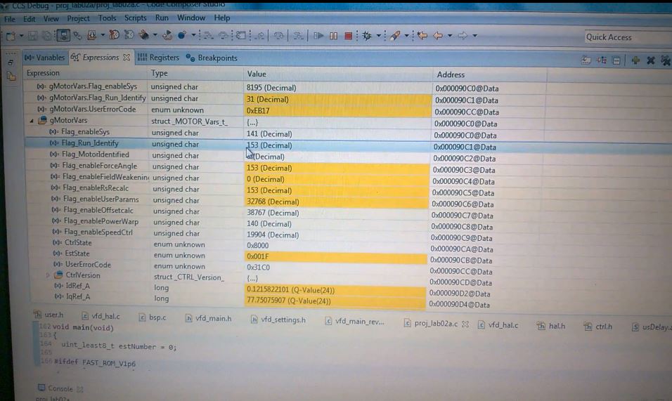
    In the end of your test video clip, The whole values of MotorVars are strange as below capture. I'm not sure why your debug shows the strange values. What's compiler version you are using? Can you attach .map file and user.h file?

  • Dear Steve,

    Have a nice week to you. Thanks for your query, I also feel strange with my result of motor ID.

    This is my definition for your requirements:

    //! \brief Defines full scale (or BASE) value for the IQ30 variable of Voltage inside the system
    //! \brief All voltages are converted into (pu) based on the ratio to this value. In other words, this value MUST be larger than the maximum value of any voltage calculated inside the control system.
    #define USER_IQ_FULL_SCALE_VOLTAGE_V      (1000.0)   	// 1000.0V for vfdkit_rev1.0 typical usage (Added by Duongtb; 10-Nov-2015)
    
    //! \brief Defines the maximum phase voltage at the input to the AD converter
    //! \brief The value that will be represented by the maximum ADC input (3.3V) and conversion (0FFFh)
    //! \brief Hardware dependent, this should be based on the voltage sensing and scaling to the ADC input
    #define USER_ADC_FULL_SCALE_VOLTAGE_V     (548.52)      // 548.52V for vfdkit_rev1.0 voltage scaling (Added by Duongtb; 10-Nov-2015)
    
    //! \brief Defines the voltage scale factor for the system
    //! \brief Compile time calculation for scale factor (ratio) used throughout the system
    #define USER_VOLTAGE_SF               	  ((float_t)((USER_ADC_FULL_SCALE_VOLTAGE_V)/(USER_IQ_FULL_SCALE_VOLTAGE_V)))
    
    #define USER_ADC_FULL_SCALE_DCBUS_VOLTAGE_V (1000.0)	// 3.3V/(0.005*2.64/4) = 1000.0V
    
    //! \brief Defines the dcbus voltage scale factor for the system
    //! \notes Added by Duongtb (28-Jan-2016)
    #define USER_DCBUS_VOLTAGE_SF  			((float_t)((USER_ADC_FULL_SCALE_DCBUS_VOLTAGE_V)/(USER_IQ_FULL_SCALE_VOLTAGE_V)))
    
    //! \brief Defines the full scale (or BASE) current for the IQ variables, A
    //! \brief All currents are converted into (pu) based on the ratio to this value
    #define USER_IQ_FULL_SCALE_CURRENT_A         (62.5)   	// 62.5 Example if using ACS756-50A typical usage (Added by Duongtb; 10-Nov-2015)
    
    //! \brief Defines the maximum current at the AD converter
    //! \brief The value that will be represented by the maximum ADC input (3.3V) and conversion (0FFFh)
    //! \brief Hardware dependent, this should be based on the current sensing and scaling to the ADC input
    #define USER_ADC_FULL_SCALE_CURRENT_A        (125.0)    // 125A peak-to-peak vfdkit_rev1.0 current scaling when using ACS756-050B (Added by Duongtb; 10-Nov-2015)
    
    //! \brief Defines the current scale factor for the system
    //! \brief Compile time calculation for scale factor (ratio) used throughout the system
    #define USER_CURRENT_SF               	((float_t)((USER_ADC_FULL_SCALE_CURRENT_A)/(USER_IQ_FULL_SCALE_CURRENT_A)))
    
    //! \brief Defines the maximum dcbus current at the input to the AD converter
    //! \notes Added by Duongtb (28-Jan-2016)
    #define USER_ADC_FULL_SCALE_DC_CURRENT_A 		(50.0)	//For the Shunt resistor is 10m Ohms and the gain = 10*0.66
    
    
    //! \brief Defines the dcbus current scale factor for the system
    //! \notes Added by Duongtb (28-Jan-2016)
    #define USER_DCBUS_CURRENT_SF  			((float_t)((USER_ADC_FULL_SCALE_DC_CURRENT_A)/(USER_IQ_FULL_SCALE_CURRENT_A)))
    

    And these are the *.map and user.h files:

    my_files.rar

    Notes that: I also attach Excel file to select the parameters for my hardware in the above file ZIP.

    Finally, I'm using the Compiler TI v6.2.11 for generating the proj_lab02.map file which is attached in this email. Beside I also tried with the Compiler TI v6.4.6 and the newest Compiler TI v15.12.2.

    Please help me to find where the problem is!

    Many thanks for your support,

  • Dear Steve,

    Have you seen my files which I sent you? What did you find any problem in my setup?

    In order for you can be easy to check my hardware configuration, I would like to send you one more file at:

    5810.Simple-VSD Product - Signal Condition.pdf

    Waiting for your reply as soon as possible,

  • Dear Steve,

    Today I have new info for you. I have just reinstalled CCSv6 ( 6.1.3.00033) with Evaluation License  and recompiled proj_lab2b with the compiler version 15.12.1.LTS.

    After running with new CCS and compiler, I got the better result in Motor ID process in comparison with the previous result. However, I is not still successful in the whole of Motor ID process. Because, at the end of process the CTRL and EST fell in Error_State!!! Please see some samples which I captured from the process of Motor ID.

    I observed in the whole process of Motor ID, the EST never went to the EST_State_LockRotor as described in the PAGE 35 of the document named InstaSPIN Projects and Labs User's Guide. It passed the states: Idle->RoverL->Rs->RampUp->IdRated->RatedFlux, and finally went to the State_Error!!!

    I posted a video-clip showed the other session of ID process here: www.dropbox.com/.../WP_20160519_09_05_13_Pro.mp4

    Beside I also provide the name-plate of my motor which I am wanting to identify its parameters:

    Please help me to resolve completely this problem by your experience, because I really expect in Motor ID feature of MotorWare.

    Hoping you reply as soon as possible,

    Thank you in advance!

  • Hi Tran,

    Sorry for late feedback. I was on super busy for other projects support.

    First, I recommend the following guides on your setting in user.h file.
    1) The USER_IQ_FULL_SCALE_VOLTAGE_V(1000V)  is too high compare to USER_ADC_FULL_SCALE_VOLTAGE_V(548.52V). How about changing to about 600V if the USER_checkForErrors() function does not return ERROR during initialization. If USER_IQ_FULL_SCALE_VOLTAGE_V is too high, It can give a negative effect to the calculation accuracy of voltage feedback.

    2) The recommend value of USER_NUM_ISR_TICKS_PER_CTRL_TICK for motor ID is (1). The 54F MCU usage resource is enough for 10KHz control and estimator loop.


    Second, I am still suspicious of your HW. The one more thing you can check hardware noise level and scale error is that you compare the real values on oscilloscope and MCU variables stored on memory. You can refer to lab05f for storing some variables to RAM. The procedure I think for this test is as following.

    1) Adding the graph variables and memory storing code to main code.

    2) Adding the V/F open-loop variables and codes to each lab0x file and CTRL_runOnLine_User() function in ctrl.h file.

    3) You may change the value of V_alfa and V_beta in the stationary quadrature axis and angle(theta) for V/F test. If so, pleas store I_alfa, I_beta, V_beta and V_alfa by using CTRL_getIab_in_pu() and CTRL_getVab_in_pu() functions. If you draws these four values on Excel file, you can see if how much noise is on feedback circuits and if there is no scale error on feedback.


    Please let me know if my comments are unclear.

    - Steve

  • Dear Steve,

    Thanks for your feedback. I want to explain for your doubts as following:
    1. I selected USER_IQ_FULL_SCALE_VOLTAGE_V = 1000 (V) is for converting from PU to real values of voltages in convenience. In my hardware circuit, I designed the conditional stage for measuring VdcBus up to 1000V. Moreover I estimated that when the motor is in generating mode, the regenerative energy return DCbus and it can make the VdcBus up to 800V (in comparison with the value 540V in normal condition). So that I set the USER_IQ_FULL_SCALE_VOLTAGE_V = 1000V.

    In my design, the gain for measuring VdcBus and the gain for measuring the phase voltages are different!!! However the value USER_IQ_FULL_SCALE_VOLTAGE_V is shared for both.

    I check the value of VdcBus which is read by DSP and compared with the result of reading from a digital volt-meter for DC Bus, they are the same.

    So what do you think about my setting?

    2. I will change the USER_NUM_ISR_TICKS_PER_CTRL_TICK = 1 (instate of being 2 as before) according to you suggestion.

    3. I will also check again for my hardware as your process, but if you saw my reports of the current and voltage signals above, how do you feel about them? Whether it have any problem for motor ID or estimation of InstaSPIN or not?

    I will report new result for you and everybody on forum as soon as possible. However I want to ask for two more questions in this letter:

    a) When doing a session of motor ID, I need to unload for the motor (or run the motor with no load) or set full load for the motor?

    b) Because I am afraid of damaging my hardware in motor ID process, so instead of supplying the full voltage for Dcbus (500V), I only supplied about 200Vdc while identifying the motor parameters. Whether this affects to the result of identification or not?


    Please keep in touch and support me to the last.

    Many thanks!

  • Dear Steve,

    I have checked for the condition of setting the value for USER_IQ_FULL_SCALE_VOLTAGE_V. Specifically, according to TI's guide, the value of USER_IQ_FULL_SCALE_VOLTAGE_V must satisfy:

    USER_IQ_FULL_SCALE_VOLTAGE_V > 0.5 * USER_MOTOR_MAX_CURRENT * USER_MOTOR_Ls_d * USER_VOLTAGE_FILTER_POLE_rps

    In my case:

    //! \brief Defines the analog voltage filter pole location, Hz
    //! \brief MUST match the hardware filter for Vph
    #define USER_VOLTAGE_FILTER_POLE_Hz  (256.23)   // 256.23, value for vfdkit_rev1 hardware with Cp = 0.0247uF
    
    //! \brief Defines the analog voltage filter pole location, rad/s
    //! \brief Compile time calculation from Hz to rad/s
    #define USER_VOLTAGE_FILTER_POLE_rps  (2.0 * MATH_PI * USER_VOLTAGE_FILTER_POLE_Hz)
    
    #define USER_MOTOR_Ls_d                 (0.0860)				//!> For Induction, Identified average stator inductance  (Henry, float)
    #define USER_MOTOR_MAX_CURRENT          (13.0)					//!> Max. name-plate current of the motor.
    

    So that,

    USER_IQ_FULL_SCALE_VOLTAGE_V > 0.5 * 13 * 0.086 * (2*pi*256.23) ~= 900 V

    With the above result, I think that setting USER_IQ_FULL_SCALE_VOLTAGE_V = 1000.0 V is suitable! How about your opinion?

    That's all,


  • the large Rs means a phase was not connected.

    I noticed that your Speed_Krpm is effectively 0. During this process the motor should be running at
    USER_MOTOR_FLUX_EST_FREQ_Hz
  • Dear Chris,

    Thanks for your idea. I have just checked my hardware according to your note, with V/f control for the motor, and I verify that all three phases of the motor are connected to the VFD. In my system I only used two current sensors for measuring two phases, the current in the remain phase is calculated from two monitored phases. And below is the signals of two phase currents that I have checked:

    a) At about 30Hz

    b) At about 50Hz

    Whether beside the reason of disconnecting at one phase, what does reason make the wrong result in motor ID process?

    Also, if you know please answer me two questions in the last letter, I repeat them here:

    a) When doing a session of motor ID, I need to unload for the motor (or run the motor with no load) or set full load for the motor?

    b) Because I am afraid of damaging my hardware in motor ID process, so instead of supplying the full voltage for Dcbus (500V), I only supplied about 200Vdc while identifying the motor parameters. Whether this affects to the result of identification or not?

    Moreover, could you please share me a video-clip in which I can see the whole motor ID process on Debug Window like my share? I also want to see the operation of motor while doing a motor ID.

     I'm waiting for your reply and Steve's feedback!

  • Dear  Chris and Steve,

    I have more questions related to the function HAL_readAdcData() in the Motorware's projects.

    1) Why in these projects, the IQ12mpy operator is used, instead of using IQmpy for the bellow line codes? Because I think the factor current_sf and voltage_st as well as adcBias.I.value[i] and adcBias.V.value[i] are all in the IQ format (not IQ12 format).

    static inline void HAL_readAdcData(HAL_Handle handle,HAL_AdcData_t *pAdcData)
    {
      HAL_Obj *obj = (HAL_Obj *)handle;
    
      _iq value;
      _iq current_sf = HAL_getCurrentScaleFactor(handle);
      _iq voltage_sf = HAL_getVoltageScaleFactor(handle);
    
    
      // convert current A
      // sample the first sample twice due to errata sprz342f, ignore the first sample
      value = (_iq)ADC_readResult(obj->adcHandle,ADC_ResultNumber_1);
      value = _IQ12mpy(value,current_sf) - obj->adcBias.I.value[0];      // divide by 2^numAdcBits = 2^12
      pAdcData->I.value[0] = value;
    .
    .
    .
      // convert voltage A
      value = (_iq)ADC_readResult(obj->adcHandle,ADC_ResultNumber_4);
      value = _IQ12mpy(value,voltage_sf) - obj->adcBias.V.value[0];      // divide by 2^numAdcBits = 2^12
      pAdcData->V.value[0] = value;
    
      // read the dcBus voltage value
      value = (_iq)ADC_readResult(obj->adcHandle,ADC_ResultNumber_7);     // divide by 2^numAdcBits = 2^12
      value = _IQ12mpy(value,voltage_sf);
      pAdcData->dcBus = value;
    
      return;
    } // end of HAL_readAdcData() function

    2) Why the channel monitoring dcBus voltage use the same voltage_sf with three phase voltage channels?

    3) Why in the function updateGlobalVariables_motor(), the IQ format is used for calculating gMotorVars.VdcBus_kV, but not IQ12 format? Because the return value of gAdcData.dcBus in the HAL_readAdcData() function is in IQ12 format.

    // Get the DC buss voltage
    gMotorVars.VdcBus_kV = _IQmpy(gAdcData.dcBus,_IQ(USER_IQ_FULL_SCALE_VOLTAGE_V/1000.0));

    I am asking for the above questions, because I have in two minds about my wrong results in motor ID.

    Please answer me ASAP,

  • Dear Chris and Steve,

    I know both you return to support the forum. So please take a look to answer my last questions.

    Many thanks!
  • Hi Tran,

    Sorry for late feedback. I was stick to many urgent projects.

    A1) ADC Result Register is 12bit and the maximum is 4095. If we view the ADC result value as IQ12, IQ12(1.0) is the maximum ADC result value. If all variables are IQ24 for multiply math, IQmpy is used for get a IQ24 result. But a mixed range of IQ variables are used for multiply, we can use some trick for less cycle time. For example...
    case1:  IQ24(C) = IQ24(A) x IQ24(B) / (2^24) = IQmpy(IQ24(A),IQ24(B))
    case2:  IQ24(C)= IQ12(A) x IQ24(B) / (2^12) =  IQ12mpy( IQ12(A),IQ24(B))

    The case 2 is applied to ADC read function.

    A2) In a standard Motorware, we use the same USER_IQ_FULL_SCALE_VOLTAGE_V and USER_IQ_FULL_SCALE_VOLTAGE_V for Vbus sensing and Phase Voltage sensing because in case of full duty, the phase voltage sensing value is almost same with Vbus. In other words, just one scale factor is enough for general inverter applications. However, in special case like as your inverter that input bus voltage is too high than motor phase voltage, you can distinguish Vbus_sf from phase voltage_sf.

    A3) Please refer to the A1).

    Thanks,

    Steve

  • Dear Steve,

    Thanks for your explanation!

    I have just verified your answer to close this topic here.

    Many thanks for your support in the past time.