Hello,
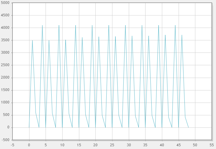
I have to use f28069 as a part of mechanical project . I am applying a sine wave of 2 vrms from function generator at different frequencies as input signal but getting a distorted output wave in GUI of code composer. Program using for continuous adc :-
void main(void)
{
Uint16 i = 0;
//=================================
// INITIALISATION - General
//=================================
DeviceInit(); // Device Life support & GPIO mux settings
// Only used if running from FLASH
// Note that the variable FLASH is defined by the compiler with -d FLASH
// (see TwoChannelBuck.pjt file)
#ifdef FLASH
// Copy time critical code and Flash setup code to RAM
// The RamfuncsLoadStart, RamfuncsLoadEnd, and RamfuncsRunStart
// symbols are created by the linker. Refer to the linker files.
MemCopy(&RamfuncsLoadStart, &RamfuncsLoadEnd, &RamfuncsRunStart);
// Call Flash Initialization to setup flash waitstates
// This function must reside in RAM
InitFlash(); // Call the flash wrapper init function
#endif //(FLASH)
//=================================
// INITIALISATION - Peripherals
//=================================
// ADC INITIALISATION
EALLOW;
AdcRegs.ADCCTL1.bit.ADCREFSEL = 0; // Use internal bandgap
AdcRegs.ADCCTL1.bit.ADCBGPWD = 1; // Power up band gap
AdcRegs.ADCCTL1.bit.ADCREFPWD = 1; // Power up reference
AdcRegs.ADCCTL1.bit.ADCPWDN = 1; // Power up rest of ADC
AdcRegs.ADCCTL1.bit.ADCENABLE = 1; // Enable ADC
for(i=0; i<5000; i++){} // wait 60000 cycles = 1ms (each iteration is 12 cycles)
AdcRegs.ADCCTL1.bit.INTPULSEPOS = 1; // create int pulses 1 cycle prior to output latch
// set S/H window to 6 clk cycles (117ns)
AdcRegs.ADCSOC0CTL.bit.ACQPS = 6;
AdcRegs.ADCSOC1CTL.bit.ACQPS = 6;
AdcRegs.ADCSOC2CTL.bit.ACQPS = 6;
AdcRegs.ADCSOC4CTL.bit.ACQPS = 6;
AdcRegs.ADCSOC7CTL.bit.ACQPS = 6;
AdcRegs.ADCSOC9CTL.bit.ACQPS = 6;
AdcRegs.ADCSOC10CTL.bit.ACQPS = 6;
AdcRegs.ADCSOC11CTL.bit.ACQPS = 6;
AdcRegs.ADCSOC12CTL.bit.ACQPS = 6;
AdcRegs.ADCSOC14CTL.bit.ACQPS = 6;
AdcRegs.ADCSOC15CTL.bit.ACQPS = 6;
AdcRegs.INTSEL1N2.bit.INT1SEL = 14; // ADCCH14 (ADC-B6) EOC causes ADCInterrupt 1
AdcRegs.INTSEL1N2.bit.INT1CONT = 1; // set ADCInterrupt 1 to auto clr
AdcRegs.INTSEL1N2.bit.INT1E = 1; // enable ADC interrupt 1
// Note that SOC3, 5, 6, 8, & 13 are valid, but these SOCs are not configured
// since these ADC outputs do not exist on the controlSTICK. The configuration
// is configured as it is for readability.
//EOC = end of conversion event; SOC = start of conversion event
AdcRegs.ADCINTSOCSEL1.bit.SOC0 = 1; // ADCInterrupt 1 causes SOC0
AdcRegs.ADCINTSOCSEL1.bit.SOC1 = 1;
AdcRegs.ADCINTSOCSEL1.bit.SOC2 = 1;
AdcRegs.ADCINTSOCSEL1.bit.SOC4 = 1;
AdcRegs.ADCINTSOCSEL1.bit.SOC7 = 1;
AdcRegs.ADCINTSOCSEL2.bit.SOC9 = 1;
AdcRegs.ADCINTSOCSEL2.bit.SOC10 = 1;
AdcRegs.ADCINTSOCSEL2.bit.SOC11 = 1;
AdcRegs.ADCINTSOCSEL2.bit.SOC12 = 1;
AdcRegs.ADCINTSOCSEL2.bit.SOC14 = 1;
AdcRegs.ADCINTSOCSEL2.bit.SOC15 = 1;
// Select the channel to be converted when SOCx is received
AdcRegs.ADCSOC0CTL.bit.CHSEL= 10; // convert ADC-A0 (CH0) when SOC0 is received
AdcRegs.ADCSOC1CTL.bit.CHSEL= 10; // convert ADC-A1 (CH1) when SOC1 is received
AdcRegs.ADCSOC2CTL.bit.CHSEL= 10;
AdcRegs.ADCSOC4CTL.bit.CHSEL= 10;
AdcRegs.ADCSOC7CTL.bit.CHSEL= 10;
AdcRegs.ADCSOC9CTL.bit.CHSEL= 10; // convert ADC-B1 (CH9) when SOC9 is received
AdcRegs.ADCSOC10CTL.bit.CHSEL= 10;
AdcRegs.ADCSOC11CTL.bit.CHSEL= 10;
AdcRegs.ADCSOC12CTL.bit.CHSEL= 10;
AdcRegs.ADCSOC14CTL.bit.CHSEL= 10;
AdcRegs.ADCSOC15CTL.bit.CHSEL= 10;
EDIS;
AdcRegs.ADCSOCFRC1.all = 0x4000; // kick start ADC by causing a SOC14 event
//=================================
// Forever LOOP
//=================================
for(;;) //infinite loop
{
AdcResults[1] = AdcResult.ADCRESULT1;
AdcResults[2] = AdcResult.ADCRESULT2;
AdcResults[3] = 0; // ADC-A6 NOT AVAILABLE on controlSTICK
AdcResults[4] = AdcResult.ADCRESULT4;
AdcResults[5] = 0; // ADC-A5 DOES NOT EXIST
AdcResults[6] = 0; // ADC-A6 NOT AVAILABLE on controlSTICK
AdcResults[7] = AdcResult.ADCRESULT0;
AdcResults[8] = 0; // ADC-B0 DOES NOT EXIST
AdcResults[9] = AdcResult.ADCRESULT9;
AdcResults[10] = AdcResult.ADCRESULT10;
AdcResults[11] = AdcResult.ADCRESULT11;
AdcResults[12] = AdcResult.ADCRESULT12;
AdcResults[13] = 0; // ADC-B5 DOES NOT EXIST
AdcResults[14] = AdcResult.ADCRESULT14;
AdcResults[15] = AdcResult.ADCRESULT15;
}
}
RESULT:-(At 400 mHz