Hey everyone,
My name is Phil and I'm a just-graduated student from Yale University's Formula SAE Electric team - Bulldogs Racing. I'm looking to develop a motor controller for a small PMSM motor (~10-15kW continuous) using InstaSPIN FOC and the TMS320F29027F. I'm most of the way through a design based around a Littelfuse IGBT module, but I have a few questions:
- One of the design criterion of Formula SAE Electric is that the low voltage (LV) system (microcontroller, dashboard, etc) needs to be galvanically isolated from the high voltage (HV) system (lithium batteries, motor, etc). This presents a problem when using InstaSPIN because the design reference directly connect the microcontroller ADC to the HV current shunts and voltage dividers. I see two potential solutions. Either isolate everything that leaves the motor controller (USB, CAN bus, etc) or isolate the HV current/voltage signals from the microcontroller. I figured that the latter would be easiest, so I looked into analog isolators in order to still hopefully use the C2000's internal ADC. Unfortunately these solutions were fairly expensive per unit accuracy, so I opted for buying a second ADC and isolating its SPI lines through a digital isolator. I figure that a 1MSPS ADC can complete 7 conversions (three current shunts and four voltage dividers) in 7us. Using a PWM frequency of 20kHz results in this measurement taking 14% of the total control loop time. Would this be an acceptable solution? Could I go with an even slower external ADC that takes 28% of the loop time? How difficult would it be to modify the InstaSPIN code to run from an external ADC through SPI? Or am I approaching this in the wrong manner and maybe I should take the monetary hit and use the analog isolators?
- From what I can tell the current shunts are measured once per control cycle. So if I use a PWM frequency of 20kHz then the current shunts are being measured at 20kHz. I saw that the voltage dividers require a low pass filter to filter out the PWM voltage oscillations while still staying above the maximum motor frequency. Is this necessary for the current shunts as well? I'm assuming not, because it seems like FOC requires the PWM-related current to control the PID loop. If this is true, then I should use a low pass anti-aliasing filter at 20-30kHz just before the ADC, right?
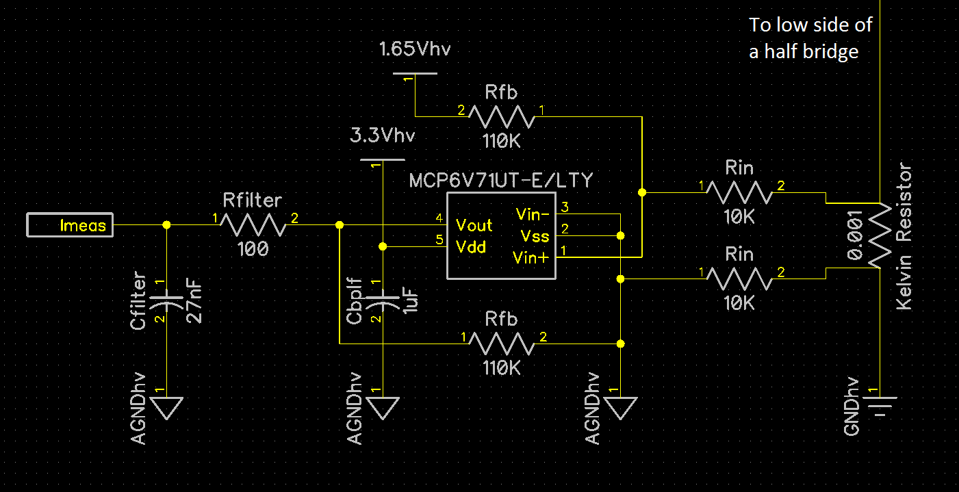
- I plan on running three current shunts in order to use a lower slew rate zero-drift op amp. However I think I may be able to get away with 2 current shunts instead. I plan on using the MAX44241AUA+ which has a slew rate of 3.8V/us. What do you think?
I'm excited to join the TI InstaSPIN community and look forward to hearing back from you guys!
Best,
Phil