Hi everyone,
I have some trouble with my C program on CCS studio.
I'm using the F28069 microcontroller and I'm trying to follow the Lab7_10.c Example that I have attached here.
The difference compared to this one is that I'm using a function generator in order to generate the square train of pulses (not the PWM module of the microcontroller) , so I just connect the GPIO24 eCAP to the output of the function generator (1KHz - 1Vpp).
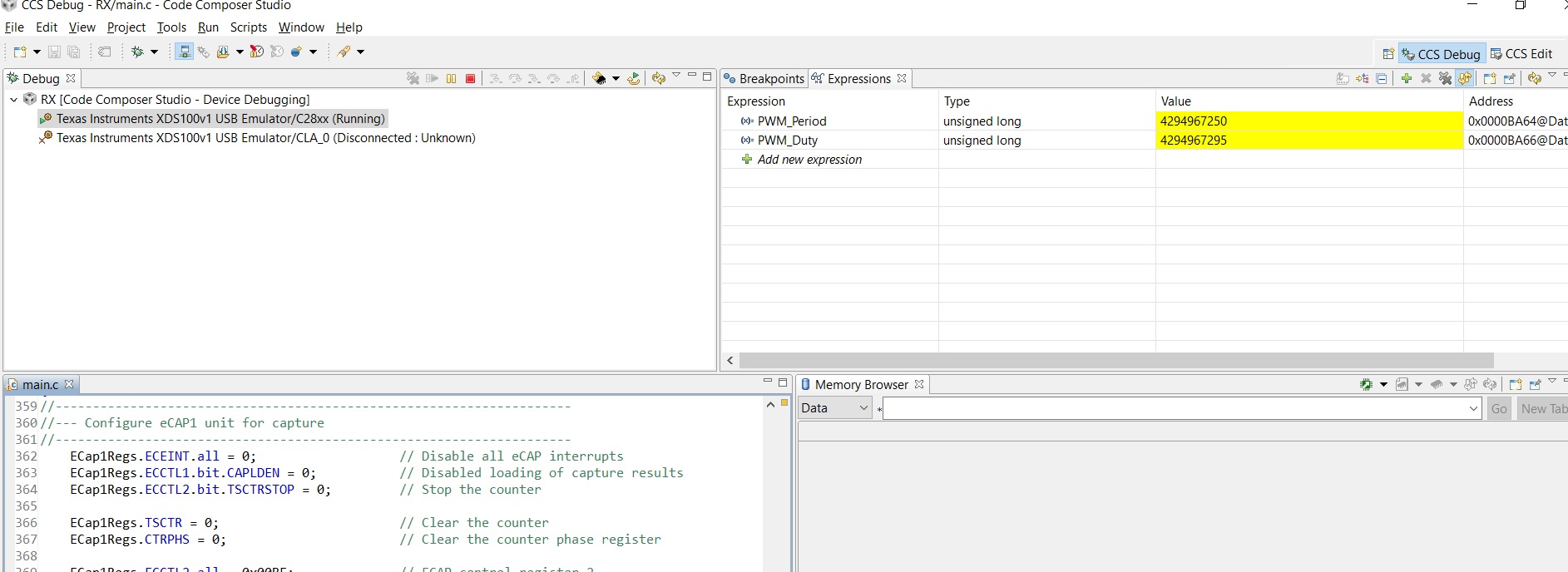
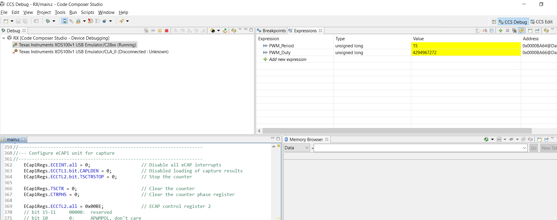
The problem is that when I print PWM_Duty and PWM_Period they do not correspond to the values generated from the function generator, rather, these values are meaningless.
Can someone help me with this program?
Thanks in advance,
Best,
Andrea
//
//      Lab7_10: TMS320F28335
//      (c) Frank Bormann
//
//###########################################################################
//
// FILE:	Lab7_10.c
//
// TITLE:	DSP28335ControlCARD; ePWM1A 1KHz output
//			and measurement with eCAP1
//			solution file for Lab7_10
//###########################################################################
//  Ver | dd mmm yyyy | Who  | Description of changes
// =====|=============|======|===============================================
//  3.0 | 12 May 2009 | F.B. | Lab7_10 for F28335;
//  3.1 | 11 Nov 2009 | F.B  | Lab7_10 for F28335 and PE Revision 5
//###########################################################################
#include "DSP2833x_Device.h"

// external function prototypes
extern void InitSysCtrl(void);
extern void InitPieCtrl(void);
extern void InitPieVectTable(void);
extern void InitCpuTimers(void);
extern void ConfigCpuTimer(struct CPUTIMER_VARS *, float, float);


// Prototype statements for functions found within this file.
void Gpio_select(void);
void Setup_ePWM1A(void);
void Setup_eCAP1(void);
interrupt void cpu_timer0_isr(void);
interrupt void eCAP1_isr(void);

// Global Variables
Uint32 PWM_Duty;
Uint32 PWM_Period;

//###########################################################################
//						main code
//###########################################################################
void main(void)
{
	int counter=0;	// binary counter for digital output

	InitSysCtrl();	// Basic Core Init from DSP2833x_SysCtrl.c

	EALLOW;
   	SysCtrlRegs.WDCR= 0x00AF;	// Re-enable the watchdog
   	EDIS;			// 0x00AF  to NOT disable the Watchdog, Prescaler = 64

	DINT;				// Disable all interrupts

	Gpio_select();		// GPIO9, GPIO11, GPIO34 and GPIO49 as output
					    // to 4 LEDs at Peripheral Explorer Board

	Setup_ePWM1A();		// init  ePWM1A

	Setup_eCAP1();		// init  eCAP1

	InitPieCtrl();		// basic setup of PIE table; from DSP2833x_PieCtrl.c

	InitPieVectTable();	// default ISR's in PIE

	EALLOW;
	PieVectTable.TINT0 = &cpu_timer0_isr;
	PieVectTable.ECAP1_INT= &eCAP1_isr;
	EDIS;

	InitCpuTimers();	// basic setup CPU Timer0, 1 and 2

	ConfigCpuTimer(&CpuTimer0,150,100000);

	PieCtrlRegs.PIEIER1.bit.INTx7 = 1;	// Enable CPU Timer 0 INT
	PieCtrlRegs.PIEIER4.bit.INTx1 = 1;	// Enable ECAP1_INT in PIE group 4
	IER |= 0x0009;						// Enable INT4 and INT1

	EINT;
	ERTM;

	CpuTimer0Regs.TCR.bit.TSS = 0;	// start timer0

	while(1)
	{
	  		while(CpuTimer0.InterruptCount == 0);
			CpuTimer0.InterruptCount = 0;

			EALLOW;
			SysCtrlRegs.WDKEY = 0x55;	// service WD #1
			EDIS;

	  		counter++;
			if(counter&1) GpioDataRegs.GPASET.bit.GPIO9 = 1;
				else GpioDataRegs.GPACLEAR.bit.GPIO9 = 1;
			if(counter&2) GpioDataRegs.GPASET.bit.GPIO11 = 1;
				else GpioDataRegs.GPACLEAR.bit.GPIO11 = 1;
			if(counter&4) GpioDataRegs.GPBSET.bit.GPIO34 = 1;
				else GpioDataRegs.GPBCLEAR.bit.GPIO34 = 1;
			if(counter&8) GpioDataRegs.GPBSET.bit.GPIO49 = 1;
				else GpioDataRegs.GPBCLEAR.bit.GPIO49 = 1;
	}
}

void Gpio_select(void)
{
	EALLOW;
	GpioCtrlRegs.GPAMUX1.all = 0;		// GPIO15 ... GPIO0 = General Puropse I/O
	GpioCtrlRegs.GPAMUX1.bit.GPIO0 = 1;	// ePWM1A active

	GpioCtrlRegs.GPAMUX2.all = 0;		// GPIO31 ... GPIO16 = General Purpose I/O
	GpioCtrlRegs.GPAMUX2.bit.GPIO24= 1;	// eCAP1 active
	GpioCtrlRegs.GPBMUX1.all = 0;		// GPIO47 ... GPIO32 = General Purpose I/O
	GpioCtrlRegs.GPBMUX2.all = 0;		// GPIO63 ... GPIO48 = General Purpose I/O
	GpioCtrlRegs.GPCMUX1.all = 0;		// GPIO79 ... GPIO64 = General Purpose I/O
	GpioCtrlRegs.GPCMUX2.all = 0;		// GPIO87 ... GPIO80 = General Purpose I/O

	GpioCtrlRegs.GPADIR.all = 0;
	GpioCtrlRegs.GPADIR.bit.GPIO9 = 1;	// peripheral explorer: LED LD1 at GPIO9
	GpioCtrlRegs.GPADIR.bit.GPIO11 = 1;	// peripheral explorer: LED LD2 at GPIO11

	GpioCtrlRegs.GPBDIR.all = 0;		// GPIO63-32 as inputs
	GpioCtrlRegs.GPBDIR.bit.GPIO34 = 1;	// peripheral explorer: LED LD3 at GPIO34
	GpioCtrlRegs.GPBDIR.bit.GPIO49 = 1; // peripheral explorer: LED LD4 at GPIO49

	GpioCtrlRegs.GPCDIR.all = 0;		// GPIO87-64 as inputs
	EDIS;
}

void Setup_ePWM1A(void)
{
	EPwm1Regs.TZCTL.all =  0;
	EPwm1Regs.TBCTL.bit.CLKDIV =  0;	// CLKDIV = 1
	EPwm1Regs.TBCTL.bit.HSPCLKDIV = 1;	// HSPCLKDIV = 2
	EPwm1Regs.TBCTL.bit.CTRMODE = 2;	// up - down mode
	EPwm1Regs.AQCTLA.all = 0x0006;		// ZRO = set, PRD = clear
	EPwm1Regs.TBPRD = 37500;			// 1KHz - PWM signal

}

void Setup_eCAP1(void)
{
//---------------------------------------------------------------------
//--- Configure eCAP1 unit for capture
//---------------------------------------------------------------------
	ECap1Regs.ECEINT.all = 0;					// Disable all eCAP interrupts
	ECap1Regs.ECCTL1.bit.CAPLDEN = 0;			// Disabled loading of capture results
	ECap1Regs.ECCTL2.bit.TSCTRSTOP = 0;			// Stop the counter

	ECap1Regs.TSCTR = 0;						// Clear the counter
	ECap1Regs.CTRPHS = 0;						// Clear the counter phase register

	ECap1Regs.ECCTL2.all = 0x0096;				// ECAP control register 2
	// bit 15-11     00000:  reserved
	// bit 10        0:      APWMPOL, don't care
	// bit 9         0:      CAP/APWM, 0 = capture mode, 1 = APWM mode
	// bit 8         0:      SWSYNC, 0 = no action (no s/w synch)
	// bit 7-6       10:     SYNCO_SEL, 10 = disable sync out signal
	// bit 5         0:      SYNCI_EN, 0 = disable Sync-In
	// bit 4         1:      TSCTRSTOP, 1 = enable counter
	// bit 3         0:      RE-ARM, 0 = don't re-arm, 1 = re-arm
	// bit 2-1       11:     STOP_WRAP, 11 = wrap after 4 captures
	// bit 0         0:      CONT/ONESHT, 0 = continuous mode

	ECap1Regs.ECCTL1.all = 0x01C4;				// ECAP control register 1
	// bit 15-14     00:     FREE/SOFT, 00 = stop TSCTR immediately
	// bit 13-9      00000:  PRESCALE, 00000 = divide by 1
	// bit 8         1:      CAPLDEN, 1 = enable capture results load
	// bit 7         1:      CTRRST4, 1 = reset counter on CAP4 event
	// bit 6         1:      CAP4POL, 0 = rising edge, 1 = falling edge
	// bit 5         0:      CTRRST3, 0 = do not reset counter on CAP3 event
	// bit 4         0:      CAP3POL, 0 = rising edge, 1 = falling edge
	// bit 3         0:      CTRRST2, 0 = do not reset counter on CAP2 event
	// bit 2         1:      CAP2POL, 0 = rising edge, 1 = falling edge
	// bit 1         0:      CTRRST1, 0 = do not reset counter on CAP1 event
	// bit 0         0:      CAP1POL, 0 = rising edge, 1 = falling edge

	ECap1Regs.ECEINT.all = 0x0008;				// Enable desired eCAP interrupts
	// bit 15-8      0's:    reserved
	// bit 7         0:      CTR=CMP, 0 = compare interrupt disabled
	// bit 6         0:      CTR=PRD, 0 = period interrupt disabled
	// bit 5         0:      CTROVF, 0 = overflow interrupt disabled
	// bit 4         0:      CEVT4, 0 = event 4 interrupt disabled
	// bit 3         1:      CEVT3, 1 = event 3 interrupt enabled
	// bit 2         0:      CEVT2, 0 = event 2 interrupt disabled
	// bit 1         0:      CEVT1, 0 = event 1 interrupt disabled
	// bit 0         0:      reserved

}

interrupt void cpu_timer0_isr(void)
{
	CpuTimer0.InterruptCount++;
	EALLOW;
	SysCtrlRegs.WDKEY = 0xAA;	// service WD #2
	EDIS;
	PieCtrlRegs.PIEACK.all = PIEACK_GROUP1;
}

interrupt void eCAP1_isr(void)
{
	ECap1Regs.ECCLR.bit.INT = 1;				// Clear the ECAP1 interrupt flag
	ECap1Regs.ECCLR.bit.CEVT3 = 1;				// Clear the CEVT3 flag

	// Calculate the PWM duty period (rising edge to falling edge)
	PWM_Duty = (int32)ECap1Regs.CAP2 - (int32)ECap1Regs.CAP1;

	// Calculate the PWM period (rising edge to rising edge)
	PWM_Period = (int32)ECap1Regs.CAP3 - (int32)ECap1Regs.CAP1;

	PieCtrlRegs.PIEACK.all = PIEACK_GROUP4;	// Must acknowledge the PIE group 4
}
//===========================================================================
// End of SourceCode.
//===========================================================================