This thread has been locked.

If you have a related question, please click the "Ask a related question" button in the top right corner. The newly created question will be automatically linked to this question.

Continuous adc graph with GUI at high frequency.

Other Parts Discussed in Thread: CONTROLSUITE

Hello,

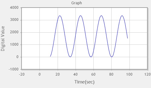
I am using adc program with f28069. When i am providing input signal as sine wave of frequency 43.3mHz , the output signal is perfect sine wave of GUI of code composer.

As i change frequency in kHz or MHz range of input signal, then output signal is distorted on.

Can we produce a perfect sine wave with gui of code composer with input signal as sine wave of KHz frequency range.

At 43.3 mHz

At 5kHz :-

  • Mahendra,

    The F28069 device operates with the following recommended settings:

    A main system clock running at 90 MHz
    A derived ADC clock running at 45 MHz
    A minimum sampling window of 7 ADC clock cycles
    A conversion windows of 13 ADC clock cycles

    With this information in mind, the 12-bit ADC on the F28069 can operate up to 3.46 MSPS which corresponds to roughly 3.5 MHz.
     
    From the Nyquist Theorem, the theoretical maximum input frequency would be half of the sampling frequency. This would mean a maximum input frequency of 1.75 MHz for the F28069. Any input signal greater than 1.75 MHz would not be able to be correctly reproduced. And realistically, it would be recommended to keep the Nyquist Frequency at 1 Mhz. So it would be best to keep the maximum input frequency to 1 MHz.
     
    How are you implementing your software conversion? How are you generating your input signal? Feel free to take a look at examples that can be found in controlSUITE. There are a few examples related to ADC conversions.

    Please let us know if you have any questions.

    Kyle

  • I an using function generator for input signal.
  • Mahendra,

    I have a few follow-up questions for you.

    What are the settings on your function generator?

    How are you connecting the output from the function generator to the microcontroller?

    How are you implementing your ADC conversion in software?

    How are you setting up the graph in CCS to view the output?

    Please let me know if any of these questions need additional clarification.

    Kyle
  • As Kyle suggested, Max. ADC sampling rate for this device is 3.46 MSPS. There is no way you can same sample 43.3 MHz and expect to re-produce the signal correctly using this ADC (based on nyquist theorem). If you look at your output graph. It shows it takes 25 sec to complete one cycle. For 43.3 Mhz, you should complete one cycle in 23.1 ns. Clearly, the sine wave you are observing is an aliased signal.

    For 5Khz, if configure your ADC to sample @ 3.46 MSPS, you should expect to see 692 sample / cycle and you should be able to re-produce the 5 KHz signal without any problem. Please check your ADC configuration.

    Regards,
    Manoj
  • Mahendra,

    Sorry, I didn't realize that you were sampling 43.3 mHz sine wave and not 43.3 MHz until my team mate highlighted.

    But my second statement still holds true.

    Regards,
    Manoj

  • Mahendra,

    Just wanted to check to see if there were any updates and if you have been able to resolve this issue. Please let us know if you have any additional questions.

    Kyle