


I am running a F28377D with a DS1775R+U temperature sensor attached to GPIO pins 0 and 1.
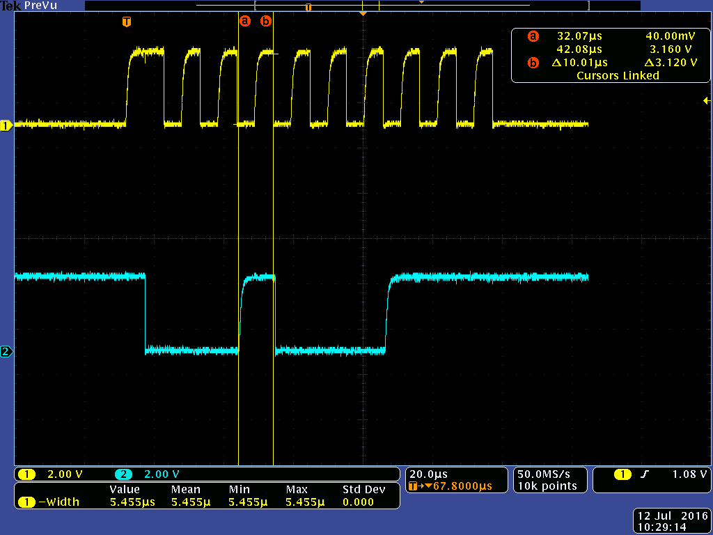
When I start my system, I am simply trying to read the base address of the sensor. The DS17775R+U is designed to continually place temperature data on the line on a read command unless otherwise configured. However, when I run my system, I see what looks to be an address being sent but I always miss the MSB of the address. I am using an I2C sniffer and when I try to send an address of 0x91(read), I get back 0x11 and when I send 0x90(write, I get back 0x10. Looking at the capture of the signal below, the clock doesnt look correct and could be the cause of the missing bit issue. All the timing diagrams that I see have the clock at a steady high value but mine always stays idle low. Is there a configuration setting to change that? Or looking at the code below does anyone see something incorrect that would cause me a bad address on the line.
Below is my I2C initialization and then the code that I am using to try and read the data.
//Disable I2C during setup
I2caRegs.I2CMDR.bit.IRS = 0;

EALLOW;
/* Enable internal pull-up for the selected I2C pins */
GpioCtrlRegs.GPAPUD.bit.GPIO0 = 0;     // Enable pull-up for GPIO0 (SDAA)
GpioCtrlRegs.GPAPUD.bit.GPIO1 = 0;     // Enable pull-up for GPIO1 (SDLA)

/* Set qualification for the selected I2C pins */
GpioCtrlRegs.GPAQSEL1.bit.GPIO0 = 3;   // Async/no qualification (I/ps sync
GpioCtrlRegs.GPAQSEL1.bit.GPIO1 = 3;   // to SYSCLKOUT by default)

/* Configure which of the possible GPIO pins will be I2C_A pins using GPIO regs*/
GpioCtrlRegs.GPAGMUX1.bit.GPIO0 = 1;   // Configure GPIO0 for SDAA operation
GpioCtrlRegs.GPAMUX1.bit.GPIO0 = 2;    // Configure GPIO0 for SDAA operation

GpioCtrlRegs.GPAGMUX1.bit.GPIO1 = 1;   // Configure GPIO1 for SDLA operation
GpioCtrlRegs.GPAMUX1.bit.GPIO1 = 2;    // Configure GPIO1 for SDLA operation
EDIS;

//module clock frequency = I2C input clock frequency/(IPSC+1)
//module clock must be between 6.7-13.3MHz
I2caRegs.I2CPSC.all = 0x0013; // Prescaler - bring 200MHz clock to 10MHz
I2caRegs.I2CCLKL = 0x002D;    // SCL frequency of 100kHz
I2caRegs.I2CCLKH = 0x002D;    // 50% duty cycle so CLKL and CLKH match

I2caRegs.I2CIER.all = 0x0000;     // Disable interrupts

I2caRegs.I2CMDR.bit.IRS = 1;  // Take I2C out of reset


***Runs in a loop to read data***
// Make sure no other transaction on bus
while (I2caRegs.I2CMDR.bit.STP != 0);

I2caRegs.I2CSAR.all   = 0x0091;

I2caRegs.I2CCNT = 2;  // Setup how many bytes to expect
I2caRegs.I2CMDR.all = 0x2C20;

while(!(I2caRegs.I2CSTR.bit.RRDY || I2caRegs.I2CSTR.bit.ARDY));

temperature[0] = I2caRegs.I2CDRR.all;
temperature[1] = I2caRegs.I2CDRR.all;

