Hi all,
I'm using TMS320C2000 Experimental kit with F28335
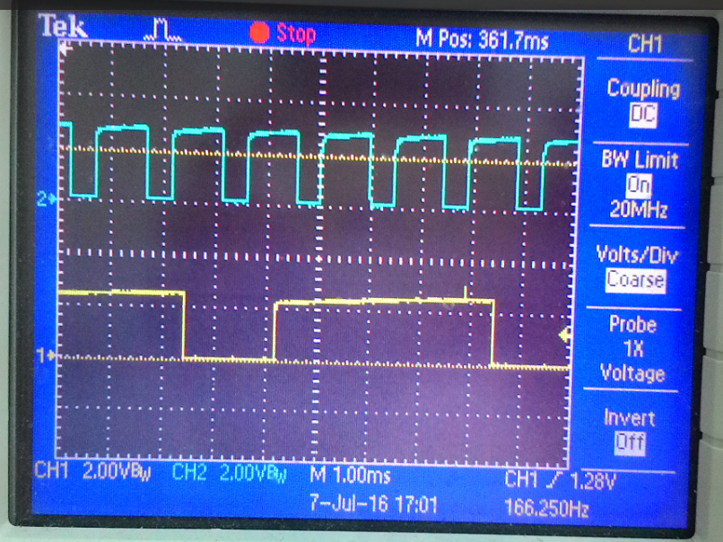
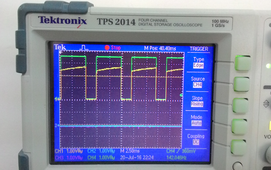
I generated two square waves using 555 and it looks very nice at Scope. One signal is 6msec period, second signal is 1.5msec period.
My ADC configuration is as follows:
//ADC parameters
#define ADC_MODCLK 0x3 // HSPCLK = SYSCLKOUT/2*ADC_MODCLK2 = 150/(2*3) = 25.0 MHz
#define ADC_CKPS 0x1 // Options 0 to F. ADC module clock = HSPCLK/2*ADC_CKPS = 25.0MHz/(1*2) = 12.5MHz
#define ADC_SHCLK 0x1 // S/H width in ADC module periods = 2 ADC clocks
SysCtrlRegs.HISPCP.all = ADC_MODCLK;
AdcRegs.ADCTRL1.bit.ACQ_PS = ADC_SHCLK; // sampling window
AdcRegs.ADCTRL3.bit.ADCCLKPS = ADC_CKPS;
AdcRegs.ADCTRL1.bit.CPS = 0; // divide by 1 the FCLK Options 0 (divide by 1) or 1 (divide by 2)
AdcRegs.ADCTRL3.bit.SMODE_SEL = 1; //Simultaneous mode to convert 2 signals in parallel
First question is what will be the sampling rate?
I saw the following comment in one of the examples:
//If Simultaneous mode enabled: Sample rate = 1/[(3+ACQ_PS)*ADC clock in ns]
According to this teh sampling rate is: 1/[4*80nsec] = 3.125MHz -->0.32usec - should be enough for my signals
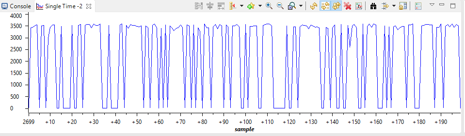
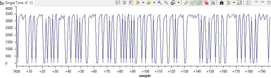
Using the graph feature I see the following:
Signal 6msec
Signal 1.5msec:
Why is this so inaccurate? Where is the problem?
Thanks