This thread has been locked.

If you have a related question, please click the "Ask a related question" button in the top right corner. The newly created question will be automatically linked to this question.

F28377D Comparator Speed

Other Parts Discussed in Thread: CONTROLSUITE

Hi,


I'm using comparator subsystem to trip the epwm. This peripheral is useful especially for hardware cycle by cycle current limiting. I configured the CMPSS1 as a window comparator application, so COMPH generates trip signal for upper limit and COMPL comparator generates for the lower limit.
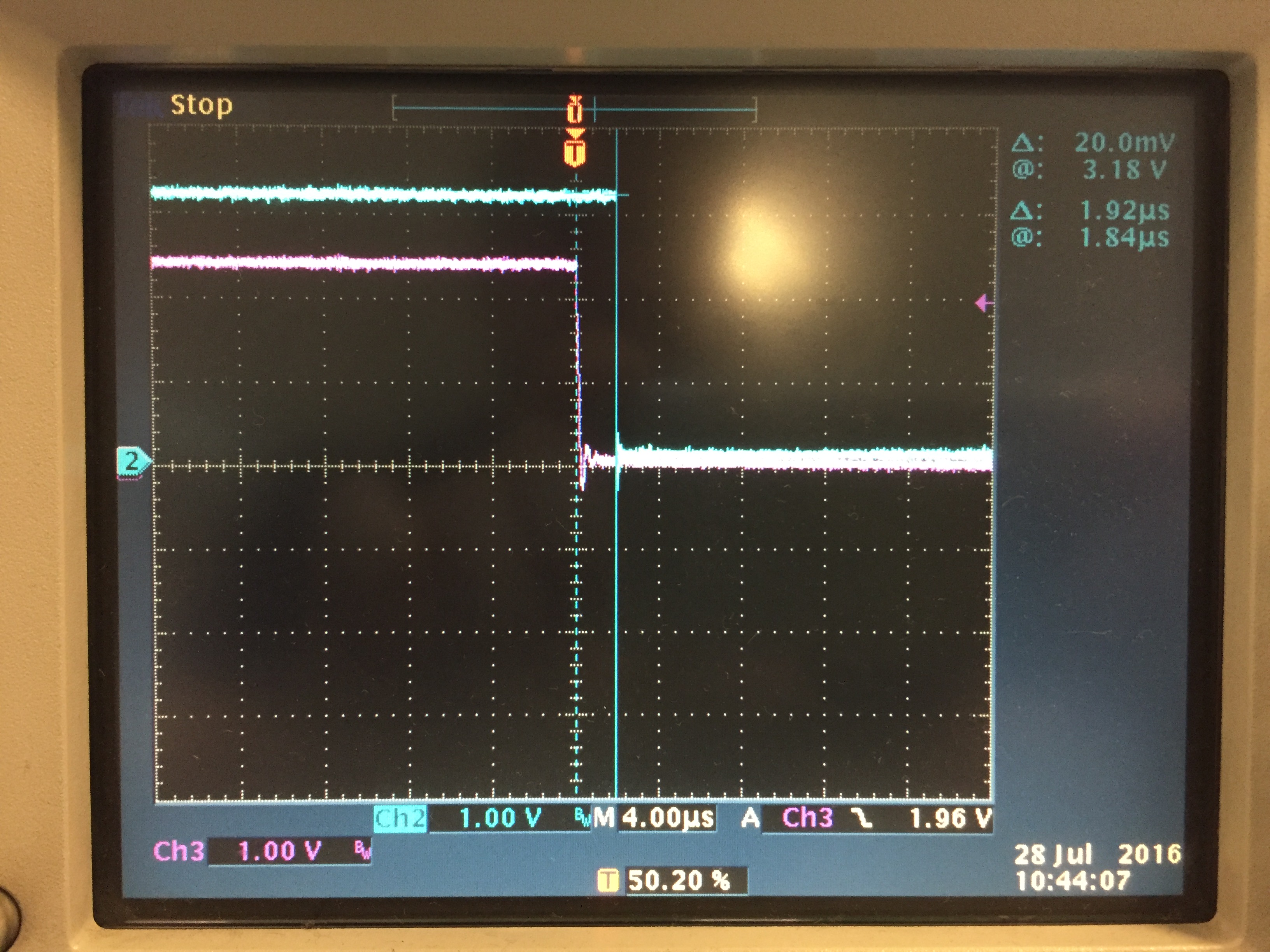
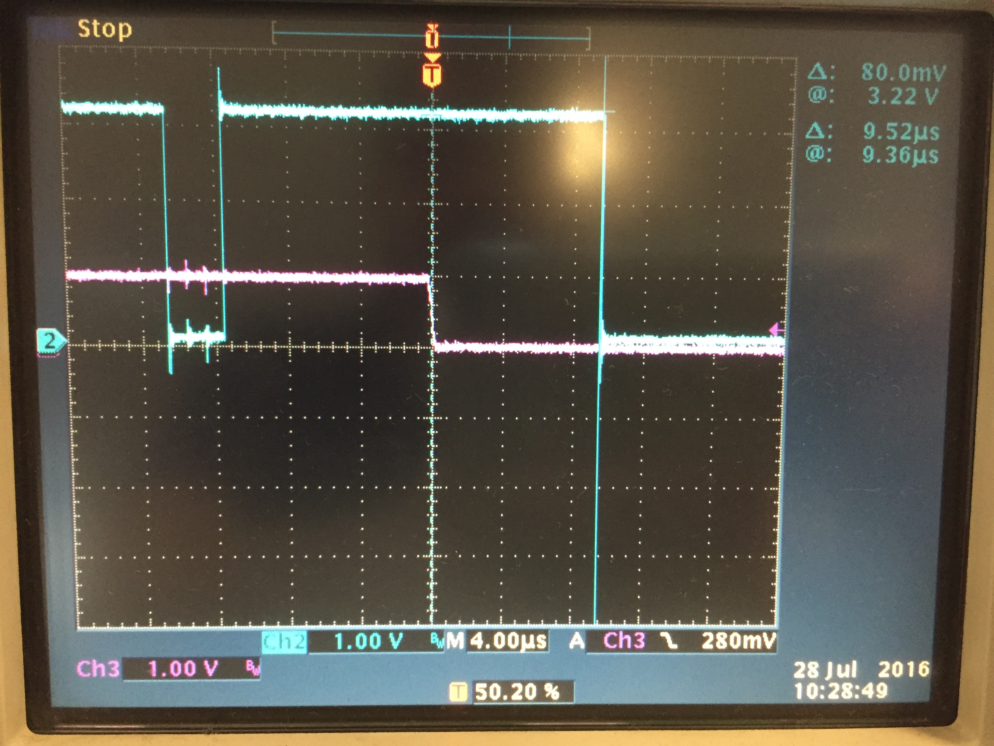
Here the issue; COMPH generates trip signal within a couple of hundred nanoseconds but COMPL generates trip within few microseconds. All the configuration is same for both comparators. I also tried bypassing the digital filter using ASYNCH path but the result is same. The trip signal goes to epwm module using output xbar module.

Is there any hardware data about this topic, or should I check the software? How can I make COMPL to response fast like COMPH?

Thanks,

  • Hi CEM,

    The high and low comparators have roughly the same propagation delay. Are you using hysteresis? Since you are doing a window trip, one way to verify that the comparators have the same propagation delay is to swap the high and low comparators. So if you were using COMPH for the high limit and COMPL for the low limit, COMPL now becomes your high limit and COMPH your low limit.

  • Hi Mr Frank,

    Yes I'm using 4x hysteresis. There is only one register for hysteresis, "Cmpss1Regs.COMPHYSCTL.bit.COMPHYS". I suppose this register define hysteresis for both comparators. I will make further tests and will give the results.

    Regards,
  • By the way I'm using my own design board which uses F28377D Silicon Revision C.
  • Is it possible to swap the COMPH and COMPL on your board?
  • Hi,

    I made some tests, and I find that response time of the comparator depends on comparator reference which is define by the internal dac.
    As the dac value decreases the response time increases. This is true for COMPH and COMPL.

    1. COMPH trip times are about 100-250ns depending on digital filter sampling window and threshold with dac reference 2500.
    COMPL trip time is about 8usec with dac reference 600.
    2. I tried to bypass digital filter and the result is same.
    3. I changed hysteresis settings "4x" and "none", result is same.
    4. I tried Cmpss1 and Cmpss2 which uses different adc pins, result is same.
    5. I tried outputxbar3 and outputxbar4 to send the trip signal to epwm module, result is same.
    6. Tried different pins for outputxbar and inputxbar, result is same.
    7.Also in the output xbar tried to use mux0 CMPSS1.CTRIPOUTH_OR_CTRIPOUTL connection and compared this setting with the
    mux0 CMPSS1.CTRIPOUTH, mux1 CMPSS1.CTRIPOUTL connection. mux0 and mux1 inputs a logic or gate. Result is same.
    8.I only used the COMPL, didn't initialize COMH and result is same.

    I think delayed output issue is on COMPL is about the comparator. The other peripherals within the CMPSS is not related with this.
    As you can see I tried different settings to connect the comparator output signal to the epwm module, but I don't think the delay caused by other peripherals.

    I will look into internal dac settings.
  • Hi CEM KOOSE,

    Yes, to some degree the response time of a comparator is related to the overdrive (delta between your input signal and dac reference). The greater the overdrive, the faster the comparator responds though I can't explain why you are seeing the reverse. Could you describe how you are measuring the response times?

  • Hi,

    I set the COMPH dac reference to 3.0V and COMPL reference to 0.3V. Signal midpoint is 1.65V. CMPSSx module uses VDDA(3.3V) for the dac reference source.
    First I used a high quality signal generator to generate a step signal 1.65V to 3.3V which is connected to CMPIN1P. Oscilloscope single shot mode triggers at rising edge of the step signal. As soon as input step signal passes the 3.0V comparator reference, epwm output signal with duty cycle %99 trips and becomes forced low within 150nsec. If I decrease the COMPH reference to 2.5V from 3.0V, trip time increases nsecs to usecs.
    In the case of COMPL with 0.3V reference, input signal suddenly decreases from 1.65V to 0V. Oscilloscope single shot triggers at the falling edge of the input signal. In this case epwm output trips about 8usec.
    COMPL and COMPH comparators works same, only response time change is caused by dac references. If I increase COMPL reference it produces faster response.
    Also, to produce sharper input signal(higher slew rate) I set up a circuit with voltage divider and buttons. Buttons are used to produce step action. Result is same.
  • Hi CEM,

    Can you look at CTRIPOUTH and CTRIPOUTL through the Xbar on the scope? Also, how are you making sure the reference levels are 0.3v and 3.0v. Due to offset error in the CMPSS, (dacval/4096)*3.3 might not exactly give you the reference voltages. Though it wouldn't account for this much variation, you can make that more accurate by calibrating the dacvals with 0.3v and 3.0v voltages. Please look at the outputs of CTRIPOUTH and CTRIPOUTL and report back.
  • Hi,

    I assigned CTRIPOUTH and CTRIPOUTHL to outputxbar3 and observed at scope. Result is exact same with the epwm case. For higher dac references, trip times decreases, for lower dac references trip time increases. In my case window reference levels 0.3V and 3.0V is not very sensitive, what I need is fast reponse independent of the comparator dac references.

    I will give my CMPSSx configuration, please check it.

    EALLOW;

    CMPSS_PTR[cmpss_num]->COMPCTL.bit.COMPDACE = 1; //Enable CMPSS

    //Comparator Digital Filter Initialization
    CMPSS_PTR[cmpss_num]->CTRIPHFILCTL.bit.SAMPWIN = 30; //Sampling Window
    CMPSS_PTR[cmpss_num]->CTRIPHFILCTL.bit.THRESH = 18; //Sampling Treshold
    CMPSS_PTR[cmpss_num]->CTRIPHFILCLKCTL.bit.CLKPRESCALE = 1;
    CMPSS_PTR[cmpss_num]->CTRIPHFILCTL.bit.FILINIT = 1; //Initialize all samples to the filter input value

    CMPSS_PTR[cmpss_num]->CTRIPLFILCTL.bit.SAMPWIN = 30;
    CMPSS_PTR[cmpss_num]->CTRIPLFILCTL.bit.THRESH = 18;
    CMPSS_PTR[cmpss_num]->CTRIPLFILCLKCTL.bit.CLKPRESCALE = 1;
    CMPSS_PTR[cmpss_num]->CTRIPLFILCTL.bit.FILINIT = 1; //Initialize all samples to the filter input value

    CMPSS_PTR[cmpss_num]->COMPSTSCLR.bit.HLATCHCLR = 1; //COMPLLATCH and COMPHLATCH software clear
    CMPSS_PTR[cmpss_num]->COMPSTSCLR.bit.LLATCHCLR = 1;

    //Asynchronous comparator output feeds into OR gate with latched //digital filter output
    CMPSS_PTR[cmpss_num]->COMPCTL.bit.ASYNCHEN = 0; //High comparator asynchronous path disable
    CMPSS_PTR[cmpss_num]->COMPCTL.bit.ASYNCLEN = 0; //Low comparator asynchronous path disable

    //Outputs; CTRIPL and CTRIPH are asynch
    //Outputs; CTRIPOUTL and CTRIPOUTH are digitally filtered
    CMPSS_PTR[cmpss_num]->COMPCTL.bit.CTRIPLSEL = 2; //Output of digital filter drives CTRIPL.(Goes to EPWMXBAR)
    CMPSS_PTR[cmpss_num]->COMPCTL.bit.CTRIPOUTLSEL = 2; //Digital filter drives the Low comparator output CTRIPOUTL
    //(Goes to OUTPUTXBAR)
    CMPSS_PTR[cmpss_num]->COMPCTL.bit.CTRIPHSEL = 2; //Output of digital filter drives CTRIPH.(Goes to EPWMXBAR)
    CMPSS_PTR[cmpss_num]->COMPCTL.bit.CTRIPOUTHSEL = 2; //Digital filter drives the High comparator output CTRIPOUTH
    //(Goes to OUTPUTXBAR)
    CMPSS_PTR[cmpss_num]->COMPCTL.bit.COMPLINV = 1; //Output of comparator Low Comparator is inverted
    CMPSS_PTR[cmpss_num]->COMPCTL.bit.COMPLSOURCE = 0; //Inverting input of comparator driven by internal DAC

    CMPSS_PTR[cmpss_num]->COMPCTL.bit.COMPHINV = 0; //Output of comparator High Comparator is not inverted
    CMPSS_PTR[cmpss_num]->COMPCTL.bit.COMPHSOURCE = 0; //Inverting input of High comparator driven by internal DAC.

    CMPSS_PTR[cmpss_num]->COMPHYSCTL.bit.COMPHYS = 4; //Set hysteresis to "4 X typical hysteresis".

    //Use VDDA as the reference for DAC
    CMPSS_PTR[cmpss_num]->COMPDACCTL.bit.SELREF = 0; // VDDA is the voltage reference for the DAC

    CMPSS_PTR[cmpss_num]->COMPDACCTL.bit.SWLOADSEL = 1; //DACxVALA is updated from DACxVALS on PWMSYNC

    //Set DAC Reference
    CMPSS_PTR[cmpss_num]->DACHVALS.bit.DACVAL = 2500;
    CMPSS_PTR[cmpss_num]->DACLVALS.bit.DACVAL = 600;

    //Configure CTRIPOUTH Output Pin
    //Configure OUTPUTXBAR3 to be CMPSS1.CTRIPOUTH
    OutputXbarRegs.OUTPUT3MUX0TO15CFG.bit.MUX0 = 0;
    //Enable OUTPUTXBAR3 Mux0 for Output
    OutputXbarRegs.OUTPUT3MUXENABLE.bit.MUX0 = 1;

    OutputXbarRegs.OUTPUTINV.bit.OUTPUT3 = 1; //OUTPUT3 active low
    //Only used for ePWM TZ, because TZ is active low

    //Comment For Unidirectional Operation, Uncomment For Bidirectional Operation
    //Configure OUTPUTXBAR3 to be CMPSS1.CTRIPOUTL
    OutputXbarRegs.OUTPUT3MUX0TO15CFG.bit.MUX1 = 0;
    //Enable OUTPUTXBAR3 Mux1 for Output
    OutputXbarRegs.OUTPUT3MUXENABLE.bit.MUX1 = 1;

    // Configure GPIO26 to output CTRIP1H-CTRIP1L, OUTPUTXBAR3
    GpioCtrlRegs.GPAGMUX2.bit.GPIO26 = 0;
    GpioCtrlRegs.GPAMUX2.bit.GPIO26 = 1;

    EDIS;
  • Hi CEM,

    A few things jump out at me in your CMPSS configuration:

    1. I don't see a delay after you enable the CMPSS. The CMPSS requires 10us for power up. Do you have that somewhere after your CMPSS configuration?

    2. You have SWLOADSEL set to 1 before you write to DACHVALS and DACLVALS so the first time COMPDACH and COMPDACL will be written is when the first PWMSYNC happens. Is this your intention?

    3. You specify your window reference as 0.3v and 3.0v but DACVALS 600 and 2500 respectively with VDDA(3.3) do not evaluate to that.

    4. For debug purposes could you isolate CTRIPOUTH and CTRIPOUTL. Don't enable them on the same OUTPUTXBAR. Use one OUTPUTXBAR for each.

  • Hi,

    I detected the cause of the problem. If COMPCTL[COMPLINV] = 1 (meaning that the output of the comparator is inverted) reponse time increases with respect to comparator reference.

    1. Yes I have other function after enabling cmpss, but I put a delay_us() function just after COMPDACE. I did'n see any change in the behaviour.
    2.SYSCLK or PWMSYNC selection doesn't effect the behaviour. I change the dac reference during the application.
    3.As I said window references are variable, 0.3V and 3.0V is just a test case.
    4.I tried that, but it doesn't effect the result.

    Could you test that and reproduce the issue?
  • Hi CEM,

    I'll try to reproduce the behavior but in the mean time, can you post scope shots of what you are seeing?
  • CH2 Blue signal is epwm(or outputxbar, they are same), CH3 pink signal is comparator input(CMPIN1P). CMPSS1-COMPL is used as comparator. Comparator is configured with the code I posted before. Also, adc is sampling at 20kHz at the ADCINA2 which is the same pin with CMPIN1P.

    In the first picture comparator reference is approximately 2.0V. When the input goes below the reference, output becames low within 1.92usec.

    In the second picture comparator reference is approximately 0.3 V. In this case trip time is 9.52usec.

    Scope triggers at falling edge of the input(CH3) signal on both cases. Triger level is same as the comparator reference on both cases, 2.0V and 0.3V respectively.

  • Hi CEM,

    Thanks for providing the scope shots. I am however unable to reproduce what you are seeing. Maximum propagation delay is approximately 25ns which is around what we specify in the datasheet. Setup is as follows:

    1. Comparator is configured and a 10KHz square wave is enabled on the positive input.

    2. Compdac values are 400(0.3v) and 2500(2v).

    3. Square wave amplitude is 1v(for dacval 400) and 2.7v(for dacval 2500). In both cases the overdrive is 0.7v.

    4. This is just a rough measurement but you can clearly see the propagation delay is no where near microseconds.

    #include "F28x_Project.h"
    
    volatile struct CMPSS_REGS* CMPSS_PTR[9] = {0x0,&Cmpss1Regs,&Cmpss2Regs,&Cmpss3Regs,&Cmpss4Regs,&Cmpss5Regs,&Cmpss6Regs,&Cmpss7Regs,&Cmpss8Regs};
    
    void InitCMPSS(void);
    void ConfigGPIO(void);
    
    Uint16 cmpss_ndx = 1;
    Uint16 compdac_code = 2500;
    
    void main(void)
    {
        InitSysCtrl();
    
        DINT;
    
        InitPieCtrl();
    
        IER = 0x0000;
        IFR = 0x0000;
    
        InitCMPSS();
        ConfigGPIO();
    
        ESTOP0;
    }
    
    void InitCMPSS(void)
    {
        EALLOW;
        CMPSS_PTR[cmpss_ndx]->COMPCTL.bit.COMPDACE = 1;		// Enable cmpss
        CMPSS_PTR[cmpss_ndx]->COMPHYSCTL.bit.COMPHYS = 0; 	// Hysteresis disabled
        CMPSS_PTR[cmpss_ndx]->COMPDACCTL.bit.SWLOADSEL = 0; // Dac is updated on sysclk
        CMPSS_PTR[cmpss_ndx]->COMPDACCTL.bit.SELREF = 0; 	// Vdda is dac reference
        CMPSS_PTR[cmpss_ndx]->DACHVALS.bit.DACVAL = compdac_code;
        CMPSS_PTR[cmpss_ndx]->DACLVALS.bit.DACVAL = 0xFFF;
        CMPSS_PTR[cmpss_ndx]->COMPCTL.bit.CTRIPOUTHSEL = 0; // Ctripouth path is asynch
    	CMPSS_PTR[cmpss_ndx]->COMPSTSCLR.bit.LLATCHCLR = 1;	// Clear low latch
    	CMPSS_PTR[cmpss_ndx]->COMPSTSCLR.bit.HLATCHCLR = 1; // Clear high latch
        EDIS;
    
        DELAY_US(5000);
    }
    
    void ConfigGPIO(void)
    {
        InitGpio();
        GPIO_SetupPinMux(14, GPIO_MUX_CPU1, 6);
    
    	EALLOW;
        OutputXbarRegs.OUTPUT3MUX0TO15CFG.all = 0;
        OutputXbarRegs.OUTPUT3MUXENABLE.all = 1<<((cmpss_ndx*2)-2); // Enable ctripouth
    	EDIS;
    }
    

    I used a modified example from controlSUITE (attached). You can run that to see if you get similar results.

  • Hi Mr Frank,

    After checking my board, I figured out the issue. Its caused by hardware not the software. I have a RC low pass filter ( 100R/68n, 23.4kHz corner frequency, 6.8usec time constant) between input connector and comparator/adc pins. So the input signal I measured is input of the rc filter, not the comparator/adc input. I removed the filter and now trip time is about nsecs on both cases.

    Thanks for your effort and kind interest.

    Best regards.
  • Hi CEM,

    That makes sense. I'm glad to hear the issue is resolved. Best of luck.