Hi
I am using the can driver library. I have read the driver library guide available in ControSuit and also the examples. I am working on LAUNCHXL-F28377S.
I am trying to make the CAN bus work. I initilise the can bus like this:
void CAN_init(void){
	// pin configuration
	GPIO_SetupPinMux(70, GPIO_MUX_CPU1, 1); //GPIO70 -  CANRXA
	GPIO_SetupPinOptions(70, GPIO_INPUT, GPIO_ASYNC);
	GPIO_SetupPinMux(71, GPIO_MUX_CPU1, 1); //GPIO71 - CANTXA
	GPIO_SetupPinOptions(71, GPIO_OUTPUT, GPIO_PUSHPULL);
	EALLOW;
	GpioCtrlRegs.GPCGMUX1.bit.GPIO70 	= 1;
	GpioCtrlRegs.GPCGMUX1.bit.GPIO71 	= 1;
	EDIS;

	// turn on the CAN clock
	EALLOW;
	CpuSysRegs.PCLKCR10.bit.CAN_A = 1;
	EDIS;

	// Initialize the CAN controllers
	CANInit(CANA_BASE);

	// Setup CAN to be clocked off the PLL output clock
	CANClkSourceSelect(CANA_BASE, 0);   // 200MHz CAN-Clock directly from sysCLK
	//CANBitTimingSet();
	CANBitRateSet(CANA_BASE, 200000000, 500000); // 500K baud
	// Enable interrupts on the CAN A peripheral.
	CANIntEnable(CANA_BASE, CAN_INT_MASTER | CAN_INT_ERROR | CAN_INT_STATUS);
    //EALLOW;
    //PieVectTable.CANA0_INT = &canaISR;
    //EDIS;
	CANIntRegister(CANA_BASE, 0, cana_rx_ISR);
    // Enable the CAN-A interrupt on the processor (PIE).
    PieCtrlRegs.PIEIER9.bit.INTx5 = 1;
    IER |= M_INT9;
    // Enable the CAN-A interrupt signal
    CANGlobalIntEnable(CANA_BASE, CAN_GLB_INT_CANINT0);
    // Start CAN module A and B operations
	CANEnable(CANA_BASE);

	//
	// Initialize the receive message object used for receiving CAN messages.
	// Message Object Parameters:
	//      Message Identifier: 0x5555
	//      Message ID Mask: 0x0
	//      Message Object Flags: Receive Interrupt
	//      Message Data Length: 4 Bytes
	//      Message Receive data: rxMsgData
	sRXCANMessage.ui32MsgID = 0x0010;//2
	sRXCANMessage.ui32MsgIDMask = 0;
	sRXCANMessage.ui32Flags = MSG_OBJ_RX_INT_ENABLE;
	sRXCANMessage.ui32MsgLen = MSG_DATA_LENGTH;
	sRXCANMessage.pucMsgData = rxMsgData;
	//CANMessageSet(CANA_BASE, RX_MSG_OBJ_ID, &sRXCANMessage, MSG_OBJ_TYPE_RX);

    //
    // Initialize the transmit message object used for sending CAN messages.
    // Message Object Parameters:
    //      Message Identifier: 0x5555
    //      Message ID Mask: 0x0
    //      Message Object Flags: None
    //      Message Data Length: 4 Bytes
    //      Message Transmit data: txMsgData
    sTXCANMessage.ui32MsgID = 0x0011;//1
    sTXCANMessage.ui32MsgIDMask = 0;
    sTXCANMessage.ui32Flags = 0;
    sTXCANMessage.ui32MsgLen = MSG_DATA_LENGTH;
    sTXCANMessage.pucMsgData = txMsgData;
    //CANMessageSet(CANA_BASE, TX_MSG_OBJ_ID, &sTXCANMessage, MSG_OBJ_TYPE_TX);
}
And I am trying to send data through the CAN, like the following. It simply divides the data to packets of 8 bytes and sends them.
void CAN_send(unsigned char* data, unsigned int length_data){
	unsigned int index_data=0, index_packet=0, length_packet=0;
	while (index_data<length_data){
		length_packet = length_data-index_data > 8  ?  8  :  length_data - index_data;
		for (index_packet=0 ; index_packet < length_packet; index_packet++){
			txMsgData[index_packet] = data[index_data++];
		}
		sTXCANMessage.ui32MsgLen=length_packet;
		// wait until the transmission is free
		while (CANStatusGet(CANA_BASE, CAN_STS_TXREQUEST) & (1 << (TX_MSG_OBJ_ID-1) )) {}
		CANMessageSet(CANA_BASE, TX_MSG_OBJ_ID, &sTXCANMessage,MSG_OBJ_TYPE_TX);
	}
}
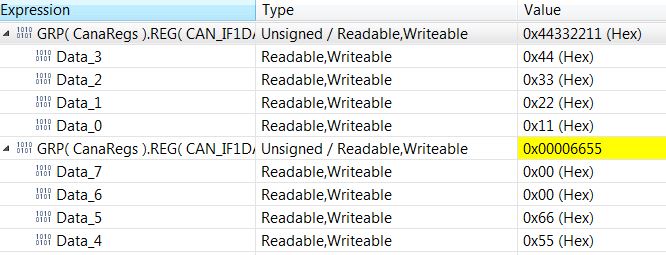
During the debug and test, when I am trying to send a packet of 6 bytes, I found that, in the function CANDataRegWrite() of the driver, where the data is going to be copied to the data register of the CAN, the data is copied in the strange way.
First 8-bit data is copied to 1st and 3rd slot of "IF1 Data A Register",
2nd 8-bit is copied to nowhere
3rd 8-bit is copied to 2nd and 4th slot of "IF1 Data A Register",
4th 8-bit is copied to nowhere
5th 8-bit is copied to 1st and 2nd slot of "IF1 Data B Register",
6th 8-bit is copied to nowhere
it is showing like this when I am using the memory browser and check in the address of the register. Even In the memory browser when I change one of the bytes, it changes it the other one automatically.
Why is it like this? What should I do?