This thread has been locked.

If you have a related question, please click the "Ask a related question" button in the top right corner. The newly created question will be automatically linked to this question.

single to differential THS4521 and TMS320F2837xS ADC

Other Parts Discussed in Thread: THS4521

Hi !

I am using the TMS320F2837xS ADC , until now i have only used it with the 12bit single ended mode.

now i am going to work with a sensor that its output voltage will swing from 1 to 5 volts , while my ADC is referenced with 3V.

i am thinking of using the 16 bit differential mode so i can handle the high output voltage .

i have added my planed schematic and i will be very thankful if someone can give some feedback .

the ADC Vcm is 1.5v.

best regards

Mark

  • Hi Mark,

    Some thoughts:

    -I think you will want to power the THS4521 with 3.3V and not 3.0V so that the amplifier can drive more of the ADC range of 0 to 3.0V.  If you use the same 3.3V supplied to VDDA on the device, this will also ensure proper power sequencing.

    -When the sensor output is 5V and the negative voltage is 3V, then the input common mode is 4V, but the max input common mode with 3.3V supply is 2V. 

    -The Vocm pin controls the output common mode.  I am not sure what your intention is in supplying 1.5V - Vcm, but I think you just want to supply 1.5V here (this should basically be whatever you supply to ADCVREFHI, divided by 2)

    -Try downloading TINA and then simulating your circuit to determine correct input and output ranges.  This will allow you to quickly iterate and try new configurations.

  • hi Devin

    thank you very much for your fast reply.
    i have simulated the circuit in TINA , but i forgotten about the THS common mode voltage limits.
    BTW , when you talk about common mode voltage you refer to the voltages on the + - inputs or the voltages before the Rg resistors ?

    best regards
    mark
  • Hi Mark,

    I think the common mode limits as applied to the THS would be whatever actually is on the +/- inputs, so I think this could be ok depending on the actual values of the resistors; this should be easy to verify in simulation.  Note that the amplifier e2e forums may be more qualified to help you with designing your circuit.  

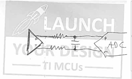
    The other thing I forgot to add is that you may want to add some differential capacitance on the output of the amplifier / input to the ADC.  This would look something like this:

    Where the R values are ~50 ohms, and C is maybe around 10 - 20pF.  This will give some mild LP filtering.  You can increase C to decrease the filter cutoff frequency, but at some point this will slow the settling enough that you will have to start increasing the ADC S+H window duration to get adequate ADC hold capacitor settling.  What is the bandwidth of your signal, and the intended sample rate?     

  • Hi Devin

    my sensor bandwidth is about 100Hz and my sampling time will be 1kHz.

    i am glad you have mentioned the RC output filter , because i see that filter added many times between the OPA output and the ADC input and i will be glad if you can share your thoughts on this subject.

    as i understand it : the capacitance is added to supply high current peaks during the sampling , and the resistor is added to keep the OPA stable. this structure forms a low pass filter with very high cut off frequency( ~MHZ) - so i will still need to add an LPF in my code..

    thank you very much

    Mark
  • Hi Mark,

    If doing a simple R-C on the input, there are basically two distinct options:

    Charge sharing:

    In this case, you put a really big capacitor right on the pin to supply all the input current to the ADC when sampling. Because all the charge comes from the external capacitor, it needs to be large enough that any inrush current to the ADC doesn't change the voltage more than the desired resolution. Therefore you would want the C on the pin to be at least 2^(N+2) times as large as the ADC Ch to get 1/4 LSBs settling. For 16-bit operation, ADC Ch is 16.5pF, so this would be 65536*4*16.5pF = 4.3uF, which is huge! Since all the charge comes from the low-impedance path of the capacitor, you can use the minimum ADC S+H window duration. From the ADCs perspective, the series R can be made as big as you want - this will reduce the LP filter cutoff frequency and help the op-amp with stability. In this case, with a 100 ohm series R and a 4.3uF capacitor, you would get a cutoff frequency around 740Hz (the filter is differential, so halve the capacitance when comparing to a single-ended filter).

    Where you can run into issues here is actually the sample rate. Even though the voltage is only dropping by 1/4 LSBs each time (with the cap size chosen above) if the op-amp can't adequately recharge the cap between samples the voltage will slowly deplete over time. If you select 1/4LSBs as the additional droop error you are willing to tolerate, then the op-amp needs to recharge from (V - 1/2 LSBs) to (V - 1/4 LSBs) during the time between samples. This means you need to recharge halfway to the target voltage, or you need -ln(0.5) = 0.7 time constants. With 100 ohm series R and the cap chose above, Tau = 2.15E-6 * 100 = 215us. 0.7*215us = 150us. 1/150us = 6.6ksps maximum sample rate.

    This should work well for you as long as the op-amp is stable with the large capacitance. You have a little margin still to increase R while still meeting the sample rate criteria. You could also halve the capacitance and accept 1 LSBs of total settling + droop error.

    Non-charge sharing:

    (In less detail)

    For a higher sample rate, the op-amp needs to supply all the charge each time. In this case, you would probably use a capacitor in the pF range. Here, you need to use the equation (Rs+Ron)*Ch + Rs*Cp to find the settling time constant, and then ensure that the S+H window is long enough to allow adequate settling. At 16-bit resolution and for 1/4LSBs settling, you would want -ln((1/65536)*(1/4)) = 12.5 time constants.

    The LP filter frequency will always be quite high. You can increase C and R to bring down the cutoff, but you will need to increase S+H duration to compensate. This won't get you anywhere near 100Hz (but as you said, you can do SW filtering instead).
  • hi Devin

    As all ways your answers are very detailed and informative!
    thank you very much for sharing your knowledge!.

    best regards
    mark