


Other Parts Discussed in Thread: TMS320F28027
Hello,
I am using TMS320F28027 LP for close loop control and PWM generation of H-bridge buck boost converter. It is a bit modified design of buck-boost having One Mosfet and One Diode in each leg.
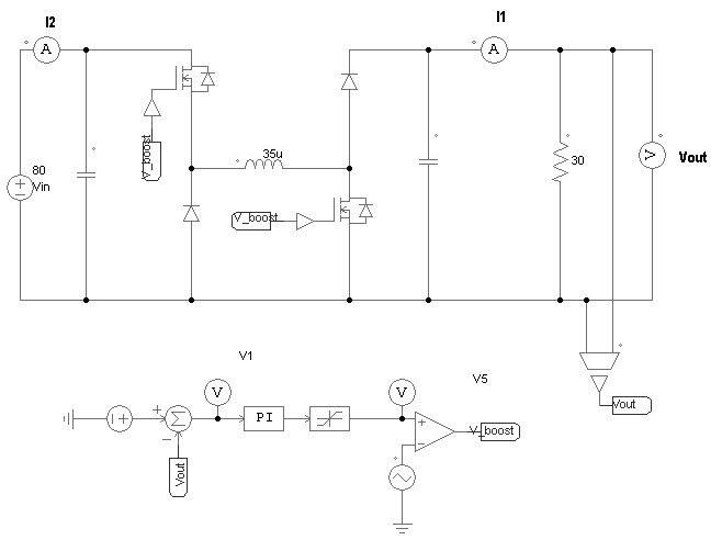
Above image depicts the topology. With below ratings:
Vin: 19-100V
Vout: 72V
Power: 500W
Fsw: 75 kHz
I am using TMS320F28027 launchpad for close loop control and PWM generation. Both the pulses for top and bottom mosfet are same (ton and toff are same). The issue is, it works fine in complete range till 200 Ohm load, but as I reduce the load (increase the current level) PWM starts to ON/OFF frequently. This may be due to Noise, but controller pulses also turns on and off frequntly on low load. Currently I am only taking the output voltage feedback and changing the pulse width as the the feedback voltage. I seen and used some example and forum code and modified it a bit.
Can someone look at the code and let me know the issue with it..?
Thanks.
// Code for H bridge buck boost converter PWM

#include "DSP28x_Project.h"     // Device Headerfile and Examples Include File

#include "f2802x_common/include/adc.h"
#include "f2802x_common/include/clk.h"
#include "f2802x_common/include/flash.h"
#include "f2802x_common/include/gpio.h"
#include "f2802x_common/include/pie.h"
#include "f2802x_common/include/pll.h"
#include "f2802x_common/include/pwm.h"
#include "f2802x_common/include/wdog.h"

// Prototype statements for functions found within this file.
#define PWM1_TIMER_TBPRD   0x0190		//TBPRD = 400 == 75Khz
__interrupt void adc_isr(void);
void InitEPwm1(void);
// Global variables used in this example:
uint16_t LoopCount;
uint16_t ConversionCount;
//uint16_t V1, V2, V3;
uint16_t V4, V5, V6;
uint16_t Voltage1[20];
 float Vout_count,Va,sum = 0;
 float err_5, A_5=0,B_5=0, v_5=0, Vpi_5 = 0;
static float in_A = 0.0, k_5 = 0.0;
float V_duty;
float comp_value, Duty;
/*** PI controller **/


	float Kp = 0.1;		// [0] proportional gain
 	float Ki = 0.05;		// [2] integral gain
 	float i10;		        // [4] I storage
	float Umax = 0.99;		// [6] upper saturation limit
	float Umin = -0.99;		// [8] lower saturation limit
	float i6;		        // [A] saturation storage

ADC_Handle myAdc;
CLK_Handle myClk;
FLASH_Handle myFlash;
GPIO_Handle myGpio;
PIE_Handle myPie;
PWM_Handle myPwm1, myPwm2;

void main(void)

{

    CPU_Handle myCpu;
    PLL_Handle myPll;
    WDOG_Handle myWDog;

    // Initialize all the handles needed for this application
    myAdc = ADC_init((void *)ADC_BASE_ADDR, sizeof(ADC_Obj));
    myClk = CLK_init((void *)CLK_BASE_ADDR, sizeof(CLK_Obj));
    myCpu = CPU_init((void *)NULL, sizeof(CPU_Obj));
    myFlash = FLASH_init((void *)FLASH_BASE_ADDR, sizeof(FLASH_Obj));
    myGpio = GPIO_init((void *)GPIO_BASE_ADDR, sizeof(GPIO_Obj));
    myPie = PIE_init((void *)PIE_BASE_ADDR, sizeof(PIE_Obj));
    myPll = PLL_init((void *)PLL_BASE_ADDR, sizeof(PLL_Obj));
    myPwm2 = PWM_init((void *)PWM_ePWM2_BASE_ADDR, sizeof(PWM_Obj));
    myPwm1 = PWM_init((void *)PWM_ePWM1_BASE_ADDR, sizeof(PWM_Obj));
    myWDog = WDOG_init((void *)WDOG_BASE_ADDR, sizeof(WDOG_Obj));

    // Perform basic system initialization
    WDOG_disable(myWDog);
    CLK_enableAdcClock(myClk);
    (*Device_cal)();

    //Select the internal oscillator 1 as the clock source
    CLK_setOscSrc(myClk, CLK_OscSrc_Internal);

    // Setup the PLL for x12 /2 which will yield 60Mhz = 10Mhz * 12 / 2
    PLL_setup(myPll, PLL_Multiplier_12, PLL_DivideSelect_ClkIn_by_2);

    // Disable the PIE and all interrupts
    PIE_disable(myPie);
    PIE_disableAllInts(myPie);
    CPU_disableGlobalInts(myCpu);
    CPU_clearIntFlags(myCpu);

// If running from flash copy RAM only functions to RAM
#ifdef _FLASH
    memcpy(&RamfuncsRunStart, &RamfuncsLoadStart, (size_t)&RamfuncsLoadSize);
#endif

    // Setup a debug vector table and enable the PIE
    PIE_setDebugIntVectorTable(myPie);
    PIE_enable(myPie);
    PIE_registerPieIntHandler(myPie, PIE_GroupNumber_10, PIE_SubGroupNumber_1,
                                    (intVec_t)&adc_isr);
    InitEPwm1();

    // Initialize the ADC
    ADC_enableBandGap(myAdc);
    ADC_enableRefBuffers(myAdc);
    ADC_powerUp(myAdc);
    ADC_enable(myAdc);
    ADC_setVoltRefSrc(myAdc, ADC_VoltageRefSrc_Int);

    // Enable ADCINT1 in PIE
         PIE_enableAdcInt(myPie, ADC_IntNumber_1);
         // Enable CPU Interrupt 1
         CPU_enableInt(myCpu, CPU_IntNumber_10);
         // Enable Global interrupt INTM
         CPU_enableGlobalInts(myCpu);
         // Enable Global real time interrupt DBGM
         CPU_enableDebugInt(myCpu);

    LoopCount = 0;
    ConversionCount = 0;

        ADC_setIntPulseGenMode(myAdc, ADC_IntPulseGenMode_Prior);               //ADCINT1 trips after AdcResults latch
   	    ADC_enableInt(myAdc, ADC_IntNumber_1);                                  //Enabled ADCINT1
   	    ADC_setIntMode(myAdc, ADC_IntNumber_1, ADC_IntMode_ClearFlag);          //Disable ADCINT1 Continuous mode
   	    ADC_setIntSrc(myAdc, ADC_IntNumber_1, ADC_IntSrc_EOC2);                 //setup EOC2 to trigger ADCINT1 to fire
   	    ADC_setSocChanNumber (myAdc, ADC_SocNumber_0, ADC_SocChanNumber_A4);    //set SOC0 channel select to ADCINA4
   	    ADC_setSocChanNumber (myAdc, ADC_SocNumber_1, ADC_SocChanNumber_A4);    //set SOC1 channel select to ADCINA4
   	    ADC_setSocChanNumber (myAdc, ADC_SocNumber_2, ADC_SocChanNumber_A2);    //set SOC2 channel select to ADCINA2
   	    ADC_setSocTrigSrc(myAdc, ADC_SocNumber_0, ADC_SocTrigSrc_EPWM2_ADCSOCA);    //set SOC0 start trigger on EPWM1A, due to round-robin SOC0 converts first then SOC1
   	    ADC_setSocTrigSrc(myAdc, ADC_SocNumber_1, ADC_SocTrigSrc_EPWM2_ADCSOCA);    //set SOC1 start trigger on EPWM1A, due to round-robin SOC0 converts first then SOC1
   	    ADC_setSocTrigSrc(myAdc, ADC_SocNumber_2, ADC_SocTrigSrc_EPWM2_ADCSOCA);    //set SOC2 start trigger on EPWM1A, due to round-robin SOC0 converts first then SOC1, then SOC2

   	    ADC_setSocSampleWindow(myAdc, ADC_SocNumber_0, ADC_SocSampleWindow_12_cycles);   //set SOC0 S/H Window to 7 ADC Clock Cycles, (6 ACQPS plus 1)
   	    ADC_setSocSampleWindow(myAdc, ADC_SocNumber_1, ADC_SocSampleWindow_12_cycles);   //set SOC1 S/H Window to 7 ADC Clock Cycles, (6 ACQPS plus 1)
   	    ADC_setSocSampleWindow(myAdc, ADC_SocNumber_2, ADC_SocSampleWindow_12_cycles);   //set SOC2 S/H Window to 7 ADC Clock Cycles, (6 ACQPS plus 1)

    // Enable PWM clock
    CLK_enablePwmClock(myClk, PWM_Number_2);

    // Setup PWM
    PWM_enableSocAPulse(myPwm2);                                         // Enable SOC on A group
    PWM_setSocAPulseSrc(myPwm2, PWM_SocPulseSrc_CounterEqualCmpAIncr);   // Select SOC from from CPMA on upcount
    PWM_setSocAPeriod(myPwm2, PWM_SocPeriod_FirstEvent);                 // Generate pulse on 1st event
    PWM_setCmpA(myPwm2, 0x0000);                                         // Set compare A value
    PWM_setPeriod(myPwm2, 0x05DC);                                       // Period = 1388 for 5Khz Sampling Frequency
    PWM_setCounterMode(myPwm2, PWM_CounterMode_Up);                      // count up and start
    CLK_enableTbClockSync(myClk);

    // Wait for ADC interrupt
    for(;;)
    {
    	PWM_setCmpA(myPwm1,Vpi_5);					//TBPRD = 200
    }
}

void InitEPwm1()
{
    CLK_disableTbClockSync(myClk);
    CLK_enablePwmClock(myClk, PWM_Number_1);
    GPIO_setPullUp(myGpio, GPIO_Number_0, GPIO_PullUp_Disable);
    GPIO_setPullUp(myGpio, GPIO_Number_1, GPIO_PullUp_Disable);
    GPIO_setMode(myGpio, GPIO_Number_0, GPIO_0_Mode_EPWM1A);
    GPIO_setMode(myGpio, GPIO_Number_1, GPIO_1_Mode_EPWM1B);
     // Setup Sync
    PWM_setSyncMode(myPwm1, PWM_SyncMode_EPWMxSYNC);
  //  PWM_setSyncMode(myPwm2, PWM_SyncMode_EPWMxSYNC);
    // Allow each timer to be sync'ed
    PWM_enableCounterLoad(myPwm1);
    PWM_setPeriod(myPwm1, PWM1_TIMER_TBPRD);
    PWM_setCounterMode(myPwm1, PWM_CounterMode_Up);         // Count up
    PWM_setIntMode(myPwm1, PWM_IntMode_CounterEqualZero);   // Select INT on Zero event
    PWM_enableInt(myPwm1);                                  // Enable INT
    PWM_setIntPeriod(myPwm1, PWM_IntPeriod_FirstEvent);     // Generate INT on 1st event

    PWM_setActionQual_Period_PwmA(myPwm1, PWM_ActionQual_Set);
    PWM_setActionQual_CntUp_CmpA_PwmA(myPwm1, PWM_ActionQual_Clear);


    PWM_setActionQual_Period_PwmB(myPwm1, PWM_ActionQual_Clear);
    PWM_setActionQual_CntUp_CmpA_PwmB(myPwm1, PWM_ActionQual_Set);

    CLK_enableTbClockSync(myClk);

}

__interrupt void adc_isr(void)

 {
	 Voltage1[ConversionCount] = ADC_readResult(myAdc, ADC_ResultNumber_1);
	 sum += Voltage1[ConversionCount];
	  if(ConversionCount == 19)
	  {
	    Vout_count = sum/ConversionCount;  // average count
	    Va = (Vout_count * 3.3)/(4096) ;  // sensed voltage in 3.3V format
	    err_5 = 3.0 - Va;

	    A_5 = (err_5 * Kp); // kp multiplication
	    B_5 = (err_5 * Ki); // Ki multiplication
	    v_5 = k_5 + (B_5 + in_A);
	    if (v_5 >= 300) v_5 = 300;  // maximum duty cycle limit
	   	if (v_5 <= 00) v_5 = 00;
	    k_5 = v_5;
	    in_A = B_5;
	    Vpi_5 = A_5 + v_5;
	    if (Vpi_5 >= 300) Vpi_5 = 300;
	    if (Vpi_5 <= 01)  Vpi_5 = 01;                 // minimum duty cycle limit
        if (Va > 3.0) Vpi_5 = 01;
    //    if (err_5< 0) Vpi_5= 0;
		ConversionCount = 0;
		sum=0;
	  }
	  else ConversionCount++;
    // Clear ADCINT1 flag reinitialize for next SOC
    ADC_clearIntFlag(myAdc, ADC_IntNumber_1);
    // Acknowledge interrupt to PIE
    PIE_clearInt(myPie, PIE_GroupNumber_10);

  //  return;
}


