This thread has been locked.

If you have a related question, please click the "Ask a related question" button in the top right corner. The newly created question will be automatically linked to this question.

meaning of SFRA_F_INJECT() ???

Other Parts Discussed in Thread: SFRA, CONTROLSUITE

Hi there,

what is the meaning of the argument of the function SFRA_F_INJECT()?

e.g. SFRA_F_INJECT(Duty_pu_DC) what is the meaning of Duty_pu_DC? 

Thanks so much

Leo

  • Leo,

    SFRA is based on small signal injection into the duty cycle and checking the response on the feedback to determine the plant response. 

    the INJECT function argument is the DC Point of the duty

    Return of the function argument is DC Point plus the small signal injection

  • Thank you Manish,

    I appreciate your help.

    1.) My understanding is that the argument of the function SFRA_F_INJECT() is the dc point of the duty, i.e. a number from 0 to 1?? e.g. let's say 0.5 if I am analysing my frequency response based on a steady state duty cycle of 0.5. So inside the interrupt I can put the following,

    //Add SFRA injection into the duty cycle for the open loop converter
    Duty_pu=SFRA_F_INJECT(0.5);

    Duty_pu is 0.5 + small signal perturbation as calculated by the function SFRA_F_INJECT in the interrupt.

    2.) Can I ask you, in the function below, is "BUCK_PWM_PERIOD" the time base period of the PWM carrier? e.g. a number such as 500? if my PWM up carrier reaches the maximum value in 500 timer counts?

    //Update PWM value
    EPwm1Regs.CMPA.half.CMPA=((long)(BUCK_PWM_PERIOD))* Duty_pu;

    Thank you again

    Leo
  • 1. yes you can orogram it like that, the reason why i recommend using a variable is that it gives you flexibility to change without having to recompile the code, that's why i recommend

    Duty_pu=SFRA_F_INJECT(Duty_pu_DC);

    but what you have understood is correct. 

    2. If the PWM is programmed in UP Count mode, BUCK_PWM_Period = EPwm1Regs.TBPRD

     the example you are referring to is UP Count, so your understanding is correct

  • Hi Manish,

    Thanks for your help. I have finally managed to 'run' the SFRA, but I believe I am doing something incorrectly in the software. I have a buck converter, and I am trying to use the SFRA in open loop, around a steady state duty cycle of 0.5, my switching frequency is 200kHz, same as the interrupt frequency. In the software below the SFRA is always on (which is what I intended to do, but perhaps there are scaling errors, or other errors which I need help to find).

    I report my main.c program below, with the parts I think are relevant for the correct config of the SFRA.

    From the main.c:

    ...
    #include "math.h"

    ...

    #define MATH_TYPE 1 //FLOAT_MATH
    #include "SFRA_F_Include.h"

    ...

    define SFRA_ISR_FREQ 200000
    #define SFRA_FREQ_START 1000
    #define SFRA_FREQ_LENGTH 100
    //SFRA step Multiply = 10^(1/No of steps per decade(40))
    #define FREQ_STEP_MULTIPLY (float)1.0233//1.059253

    SFRA_F SFRA1;
    //extern to access tables in ROM
    extern long FPUsinTable[];

    float32 Plant_MagVect[SFRA_FREQ_LENGTH];
    float32 Plant_PhaseVect[SFRA_FREQ_LENGTH];
    float32 OL_MagVect[SFRA_FREQ_LENGTH];
    float32 OL_PhaseVect[SFRA_FREQ_LENGTH];
    float32 FreqVect[SFRA_FREQ_LENGTH];

    int SFRA_flag=0;

    float Duty_pu;

    float Vpv_read;

    ...

    // SFRA initialization

    //SFRA Object Initialization
    //Specify the injection amplitude
    SFRA1.amplitude=0.1;
    //Specify the length of SFRA
    SFRA1.Vec_Length=SFRA_FREQ_LENGTH;
    //Specify the SFRA ISR Frequency
    SFRA1.ISR_Freq=SFRA_ISR_FREQ;
    //Specify the Start Frequency of the SFRA analysis
    SFRA1.Freq_Start=SFRA_FREQ_START;
    //Specify the Frequency Step
    SFRA1.Freq_Step=FREQ_STEP_MULTIPLY;
    //Assign array location to Pointers in the SFRA object
    SFRA1.FreqVect=FreqVect;
    SFRA1.GH_MagVect=OL_MagVect;
    SFRA1.GH_PhaseVect=OL_PhaseVect;
    SFRA1.H_MagVect=Plant_MagVect;

    SFRA_F_INIT(&SFRA1);

    ...

    //***************************************************************************
    // Infinite loop
    //***************************************************************************
    while (1) {

    //*************** SFRA ***************
    if(SFRA_flag == 1) {
    SFRA_F_BACKGROUND(&SFRA1);
    SFRA1.start =1;                                             // PS note I run the SFRA continuously
    }
    } // end of while(1)

    ....

    interrupt void adcb1_isr(void) {

    ...

    resultsbIndex = resultsbIndex + 1;

    v_pv[resultsbIndex] = (double) (AdcbResultRegs.ADCRESULT4) * (-0.03953) + 74.91;

    //Read ADC and computer Fbk Value

    Vpv_read=(float32)v_pv[resultsbIndex]/4096.0;

    //Add SFRA injection into the duty cycle for the open loop converter
    Duty_pu=SFRA_F_INJECT(0.5);

    //Update PWM value

    EPwm6Regs.CMPA.bit.CMPA = ( ((PWM.PR)) * Duty_pu ); // Set compare A value to a certain TBPRD counts

    EPwm6Regs.CMPB.bit.CMPB = (1.5 * PWM.PR); // condition never met -> PWM 6B always high (boost HO high, LO low)

    SFRA_F_COLLECT(&Duty_pu,&Vpv_read);
    ...

    AdcbRegs.ADCINTFLGCLR.bit.ADCINT1 = 1; //clear INT1 flag
    PieCtrlRegs.PIEACK.all = PIEACK_GROUP1;
    interrupt_exit++;

    }

    it is an adc interrupt triggered when the PWM CTR equals PRD. Below are other settings that may be relevant:

    From ePWM6 settings:

    ...

    //v2 ADC conversion related to switching EPWM6
    EPwm6Regs.ETSEL.bit.SOCAEN = 1; // enable SOC on A group 
    EPwm6Regs.ETSEL.bit.SOCASEL = 2; // EPWM6 SOCA Pulse Generated TBCTR=TBPRD //the ADC synch'd by the PWM
    EPwm6Regs.ETPS.bit.SOCAPRD = 1; // Generate pulse on 1st event

    ...

    From the ADC setup: (I am using ADC B-4, triggered by ePWM6)

    ...

    AdcbRegs.ADCSOC4CTL.bit.CHSEL = 4; 
    AdcbRegs.ADCSOC4CTL.bit.ACQPS = acqps; 
    AdcbRegs.ADCSOC4CTL.bit.TRIGSEL = 15;

    ...

    1) Now when the SFRA is run, all elements of the Plant_PhaseVect are 0.0 and never change, while the elements of the Plant_MagVect vector change and they are about -100 (a value that I did not expect).

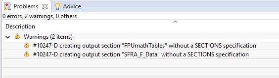
    2) Also, when I debug the main.c I get the following warning (I am not sure if I need to worry about) 

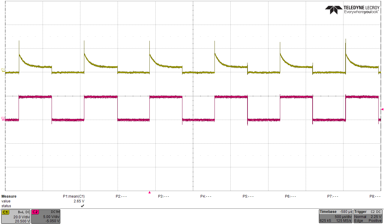
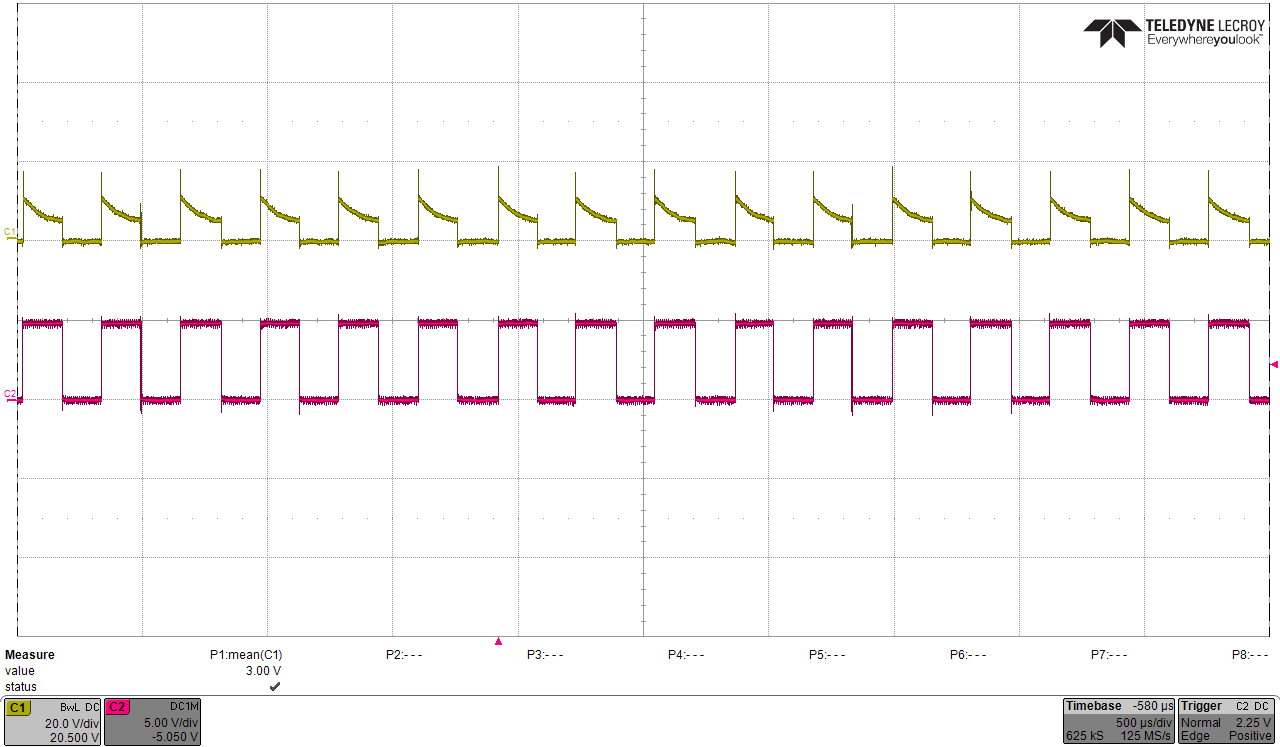
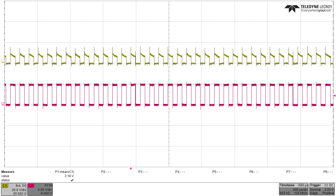
    It also seems like that the switching frequency of the converter is changing: the pink waveform is the duty cycle of the converter, changing as the SFRA sweep moves to different frequencies, for different times. The yellow waveform is the voltage (the one I am trying to use in my SFRA)

    Any help you could provide would be great.

    Thank you so much again

    Leo 

  • hi there, can anyone help on the question above? Thank you
  • Few issues

    1.

    if(SFRA_flag == 1) {
    SFRA_F_BACKGROUND(&SFRA1);
    SFRA1.start =1; // PS note I run the SFRA continuously
    }

    this may interfere with how SFRA works,

    if you want to wait for the sweep to end and immediately start another sweep, i recommend the below


    if(SFRA_flag == 1) {
    SFRA_F_BACKGROUND(&SFRA1);
    if(SFRA1.state==0)
    SFRA1.start=1;

    }


    2.

    If it is a buck example i highly recommend you review the code here

    C:\ti\controlSUITE\development_kits\BOOSTXL_BUCKCONV\v1_01_00_00\Buck_VMC_F2837xS

    C:\ti\controlSUITE\libs\app_libs\SFRA\v1_10_00_00\examples\DPSWrkShpKit_SFRA_F28069

    and compare your code against them,

    For example the below is going to take a long time , you should cast to float  which is single precision floating point.. 

    also review the code above to understand scaling,  i recommend doing things in PU format i.e. ADC ins 0-1 range , cntl output in 0-1 range etc the way it is in above examples. 

    v_pv[resultsbIndex] = (float) (AdcbResultRegs.ADCRESULT4) * (-0.03953) + 74.91;