This thread has been locked.

If you have a related question, please click the "Ask a related question" button in the top right corner. The newly created question will be automatically linked to this question.

TMS320F28069M, issues with duty cycle output (PWM)

Other Parts Discussed in Thread: TMS320F28069M, MOTORWARE, DRV8301

Dear e2e-community,

I am using the DRV8301-69m-kit with Piccolo Microcontroller (TMS320F28069M) with Motorware version V1.01.00.16. I developed an application based on project lab04. In this application I want to assign three pwm duty cycles manually. For this purpose I assign the following values.

Tabc->value[0] = _IQ(changingValue); 

Tabc->value[1] = _IQ(-0.5);

Tabc->value[2] = _IQ(-0.5);

However, the duty cycle signals PWM_AH and PWM_AL show some unwanted spikes. For different values of changingValue I obtained the following measurement results:
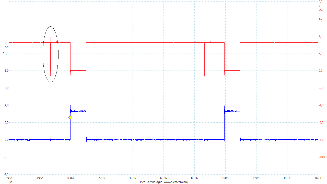
changingValue =  -0.4; PWM_AH (blue), PWM_AL (red)

changingValue =  0.0; PWM_AH (blue), PWM_AL (red)
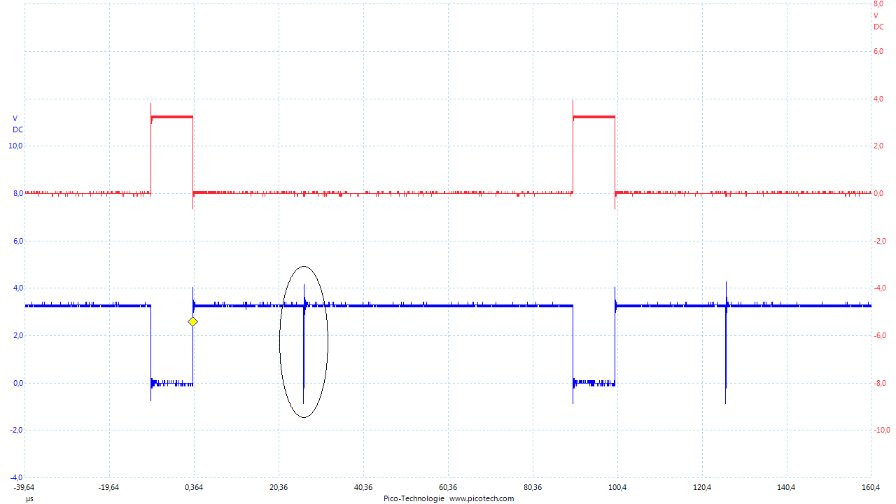
changingValue =  +0.4; PWM_AH (blue), PWM_AL (red)

The corresponding PWM register contents for the last measurement case are provided below:
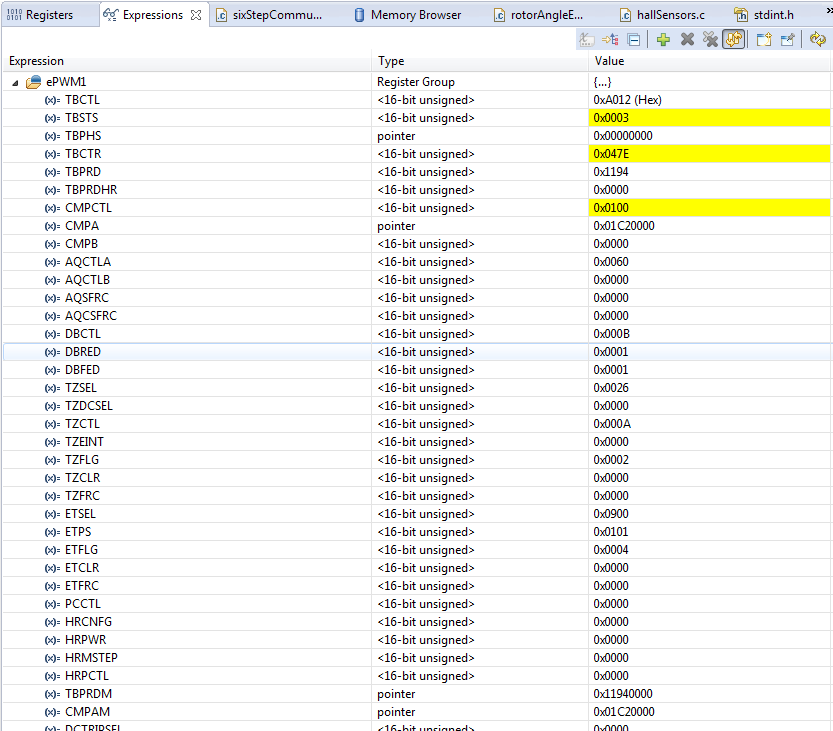
Contents below the entry CMPAM all have zero value.

I cannot explain the spikes in the waveform that I am measuring. Does anybody have a clue where they might originate from and how to resolve them?

Kind regards,

Oliver

  • Oliver,

    I can tell you what's happening, but not why. If you look at the TZFLG register it shows 2, which means the PWM1 module has seen a trip event from an input configured in cycle-by-cycle mode. From the TZSEL register, that must have come from either TZ2, TZ3, or TZ6. Possibly these are current inputs on the board. Lastly, the TZCTL setting of 0xA tells the PWMs to shut down LOW when they see one of these inputs. If you look at the scope traces you'll see it's always the high signal which shows the glitch.

    My guess is you're either seeing a momentary over-current event, or a voltage spike coupled from an edge on a different PWM channel which is causing the trip. I'm not very experienced with either MotorWare or the DRV8301 board but I'm pretty sure this is what's going on.

    Can you check the current inputs on the board (IA_FB, IB_FB, IC_FB) to see if there are any spikes there?

    Regards,

    Richard
  • Hi Richard,

    TZ2 and TZ3 are connected to the OCTWn and FAULTn line of the driver respectively.

    // OCTWn
    GPIO_setMode(obj->gpioHandle,GPIO_Number_13,GPIO_13_Mode_TZ2_NOT);

    // FAULTn
    GPIO_setMode(obj->gpioHandle,GPIO_Number_14,GPIO_14_Mode_TZ3_NOT);

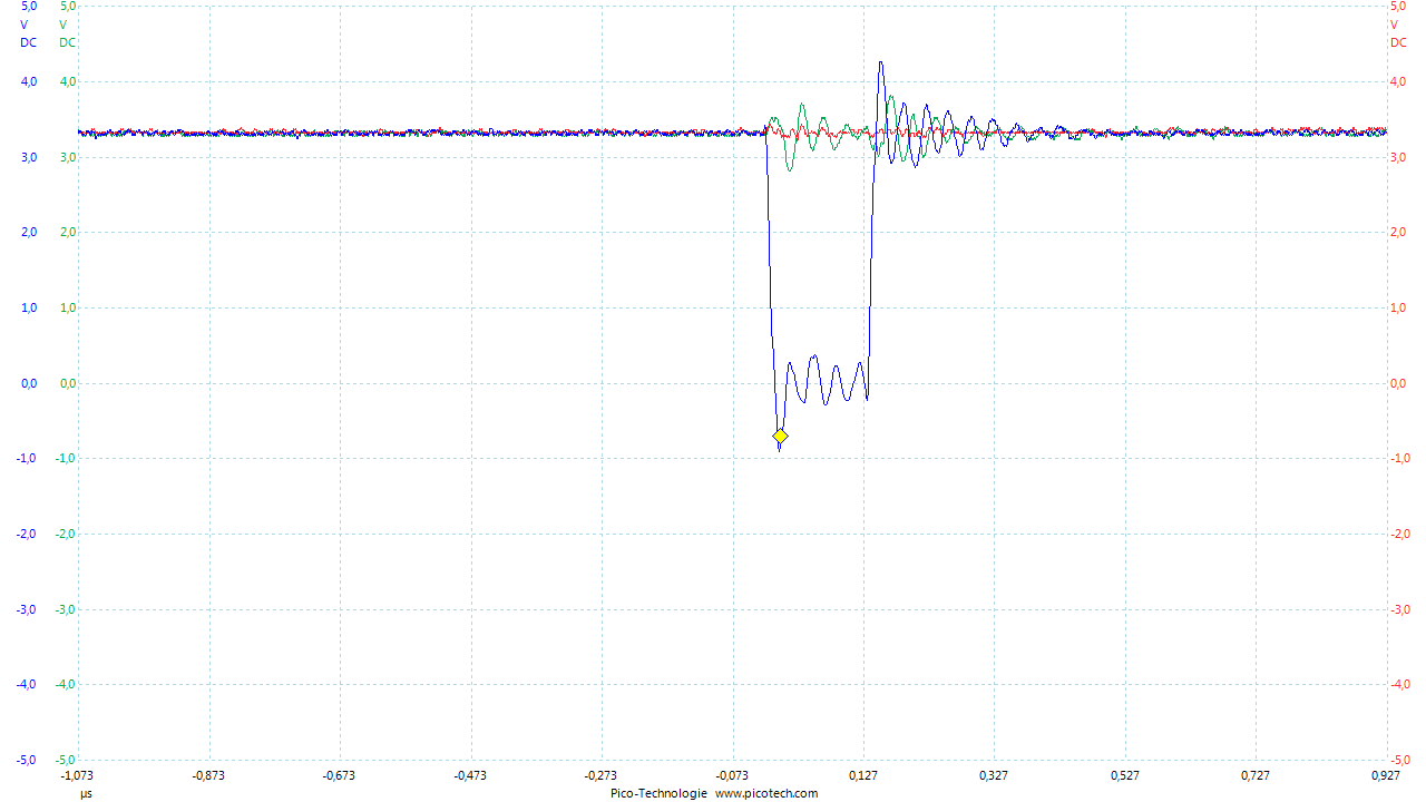
    I repeated the last measurement in the previous post. However, in case of the voltage breakdown the corresponding levels remain high:

    PWM_AH (blue), FAULTn (red), OCTWn (green). Therefore, TZ6 which is the EMUSTOP signal must cause the trouble. Is this plausible?

    Kind regards,

    Oliver

  • Oliver,

    Thank you for running the test, I think it's unlikely to be an EMUSTOP issue. It feels more like an external glitch or trip input from somewhere.

    Could you try to re-run the test with the PWM1 TZCTL register set to 0x0FFF? This will disable the influence of any trip inputs. If the glitch is still there we will know it has a software origin.

    Regards,

    Richard
  • Hi Richard,

    I re-run the test and observed exaclty the same behaviour like before. How can we narrow down possible software reasons for the this issue?

    Regards,

    Oliver

  • Hi Oliver,

    I'm not too sure where to go from here.  I have run lab 4 and those pulses are definitely not present.  On the DRV8301 board I'm looking at pins 23 & 25 on J5.  I can only assume it's somewhere in the changes to the code.

    Can you try to run just the basic lab 4 code on your setup and verify that those pulses are not there?  If they're not, please go through the changes you've made to the code.  Possibly you'll be able to back-step through the changes until you find the issue.

    Regards,

    Richard

  • Hi Richard,

    in my application I need PWM operation mode and high impedance state. Changing the pin configuration in the ADC interrupt service routine seems to be a bad idea. The described glitches resulted from the commands

    GPIO_setMode(gpioHandle, GPIO_Number_0, GPIO_0_Mode_EPWM1A);
    GPIO_setMode(gpioHandle, GPIO_Number_1, GPIO_1_Mode_EPWM1B);

    within the ADC interrupt service routine.

    I am now using the PWM operation mode only and call the force trip zone function
    PWM_setOneShotTrip(pwmHandle[0])
    whenever the high impedance state is required.

    I haven't encountered any limitations in doing so.

    Regards,
    Oliver