Other Parts Discussed in Thread: CONTROLSUITE
Hi altruists,
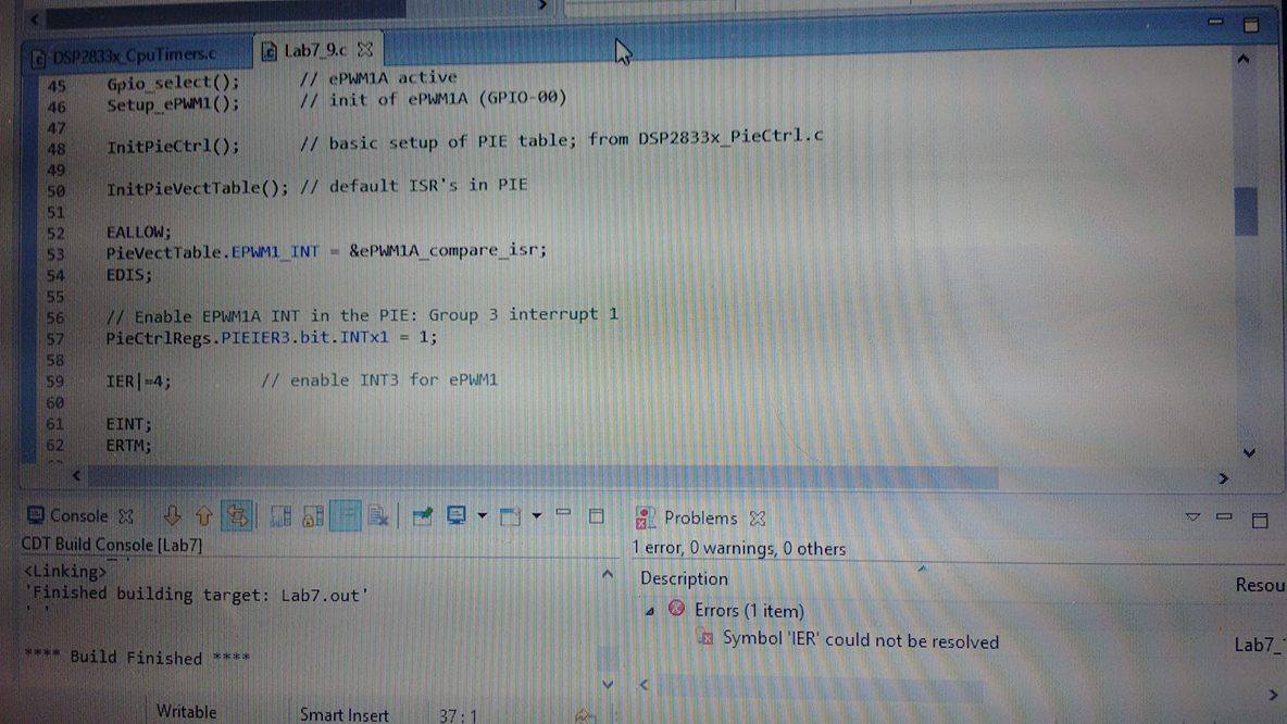
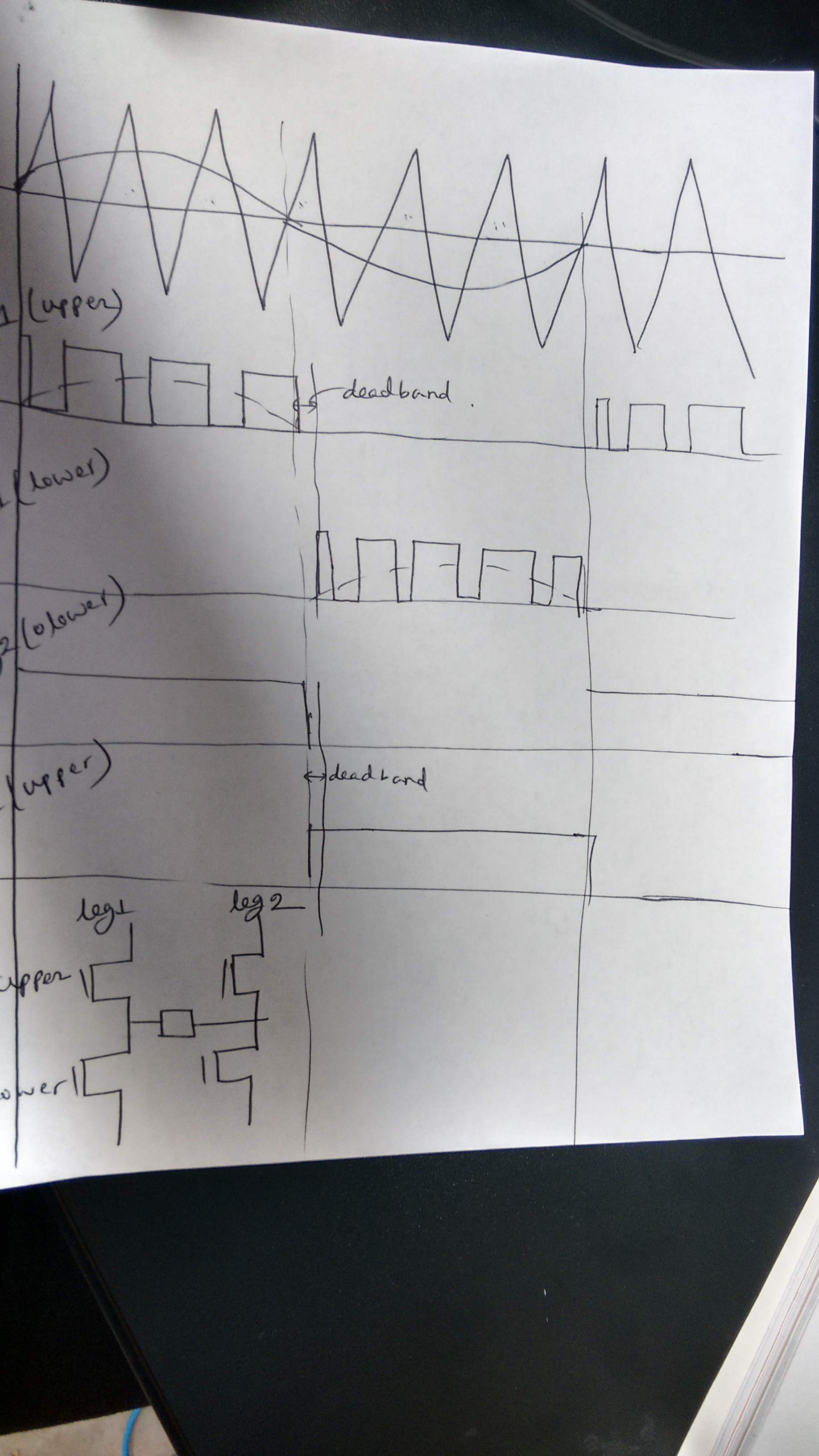
I am using F28335 to generate SPWM code for 60 Hz single phase H-bridge inverter where switching frequency should be 30 KHz. For that I need to generate SPWM with dead band for combating current “shoot-through” problems. Everything is fine with single SPWM signal without using dead band. But when I used dead band module ( 1us dead band, AHC- Active High Complementary), I got clipped signal in the lower half for both EPWM1A and EPWM1B output. I provided the oscilloscope snapshot for both the cases and these signals were collected after a low pass filter. I am also confused whether there is any dead band between the two signals? Again, I am getting switching frequency 26.55KHz after applying dead band. But previously (without deadband), it was around 30 KHz. Moreover, I got an error every time while debugging but I could run the code. The error says: Symbol 'IER' could not be resolved.
Please help me to find out the problem. I am stuck in this problem for many days.
#include "DSP2833x_Device.h"
#include "IQmathLib.h"
#pragma DATA_SECTION(sine_table,"IQmathTables");
_iq30 sine_table[512];
// external function prototypes
extern void InitSysCtrl(void);
extern void InitPieCtrl(void);
extern void InitPieVectTable(void);
// Prototype statements for functions found within this file.
void Gpio_select(void);
void Setup_ePWM1(void);
interrupt void ePWM1A_compare_isr(void);
//###########################################################################
// main code
//###########################################################################
void main(void)
{
InitSysCtrl(); // Basic Core Init from DSP2833x_SysCtrl.c
DINT; // Disable all interrupts
Gpio_select(); // ePWM1A active
Setup_ePWM1(); // init of ePWM1A (GPIO-00)
InitPieCtrl(); // basic setup of PIE table; from DSP2833x_PieCtrl.c
InitPieVectTable(); // default ISR's in PIE
EALLOW;
PieVectTable.EPWM1_INT = &ePWM1A_compare_isr;
EDIS;
// Enable EPWM1A INT in the PIE: Group 3 interrupt 1
PieCtrlRegs.PIEIER3.bit.INTx1 = 1;
IER|=4; // enable INT3 for ePWM1
EINT;
ERTM;
}
void Gpio_select(void)
{
EALLOW;
GpioCtrlRegs.GPAMUX1.all = 0; // GPIO15 ... GPIO0 = General Puropse I/O
GpioCtrlRegs.GPAMUX1.bit.GPIO0 = 1; // ePWM1A active
GpioCtrlRegs.GPAMUX1.bit.GPIO1 = 1; //ePWM1B active
GpioCtrlRegs.GPAMUX2.all = 0; // GPIO31 ... GPIO16 = General Purpose I/O
GpioCtrlRegs.GPBMUX1.all = 0; // GPIO47 ... GPIO32 = General Purpose I/O
GpioCtrlRegs.GPBMUX2.all = 0; // GPIO63 ... GPIO48 = General Purpose I/O
GpioCtrlRegs.GPCMUX1.all = 0; // GPIO79 ... GPIO64 = General Purpose I/O
GpioCtrlRegs.GPCMUX2.all = 0; // GPIO87 ... GPIO80 = General Purpose I/O
GpioCtrlRegs.GPADIR.all = 0;
GpioCtrlRegs.GPBDIR.all = 0; // GPIO63-32 as inputs
GpioCtrlRegs.GPCDIR.all = 0; // GPIO87-64 as inputs
EDIS;
}
void Setup_ePWM1(void)
{
EPwm1Regs.TBCTL.bit.CLKDIV = 0; // CLKDIV = 1
EPwm1Regs.TBCTL.bit.HSPCLKDIV = 0; // HSPCLKDIV = 1
EPwm1Regs.TBCTL.bit.CTRMODE = 2; // up - down mode
EPwm1Regs.AQCTLA.all = 0x0060; // set ePWM1A on CMPA up
// clear ePWM1A on CMPA down
EPwm1Regs.TBPRD = 2441.88; // timer period for 30.714KHz
// TBPRD = 1/2 ( 150 MHz /30.714 kHz)
EPwm1Regs.CMPA.half.CMPA = EPwm1Regs.TBPRD / 2; // 50% duty cycle first
EPwm1Regs.ETSEL.all = 0;
EPwm1Regs.ETSEL.bit.INTEN = 1; // interrupt enable for ePWM1
EPwm1Regs.ETSEL.bit.INTSEL = 5; // interrupt on CMPA down match
EPwm1Regs.ETPS.bit.INTPRD = 1; // interrupt on first event
EPwm1Regs.DBRED = 150; // 1 microseconds delay
EPwm1Regs.DBFED = 150; // for rising and falling edge
EPwm1Regs.DBCTL.bit.OUT_MODE = 3; // ePWM1A = RED
EPwm1Regs.DBCTL.bit.POLSEL = 2; // S3=1 inverted signal at ePWM1B
EPwm1Regs.DBCTL.bit.IN_MODE = 0; // ePWM1A = source for RED & FED
}
interrupt void ePWM1A_compare_isr(void)
// ISR runs every 33333.3ns (PWM-frequency =30 KHz)
// and is triggered by ePWM1 compare event
// run - time of ISR is 630 ns
{
static unsigned int index=0;
EPwm1Regs.CMPA.half.CMPA = EPwm1Regs.TBPRD - _IQsat(_IQ30mpy((sine_table[index]+_IQ30(0.9999))/2,EPwm1Regs.TBPRD),EPwm1Regs.TBPRD,0);
index +=1; // use next element out of lookup table
if (index >511) index = 0;
EPwm1Regs.ETCLR.bit.INT = 1; // Clear ePWM1 Interrupt flag
// Acknowledge this interrupt to receive more interrupts from group 3
PieCtrlRegs.PIEACK.all = 4;
}
//===========================================================================
// End of SourceCode.
//===========================================================================
Fig 1: Clipped SPWM output after filtering (when dead band is used)
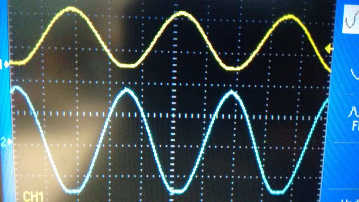
Fig 2: SPWM output without filtering (when dead band is used, frequency showing 26.542 Khz instead of 30 Khz)
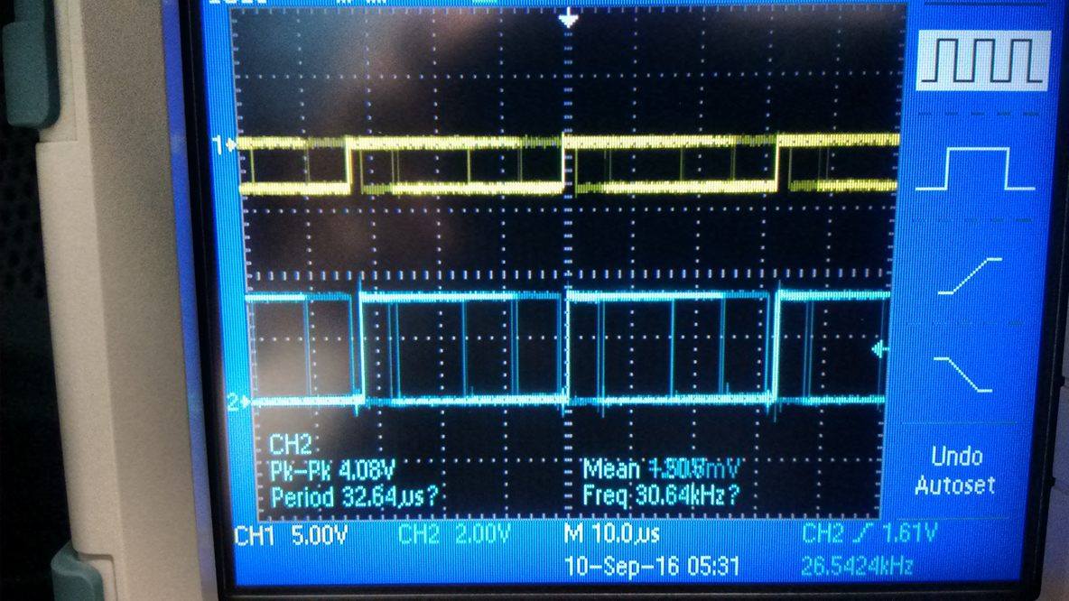
Fig 3: SPWM output after filtering (without dead band)
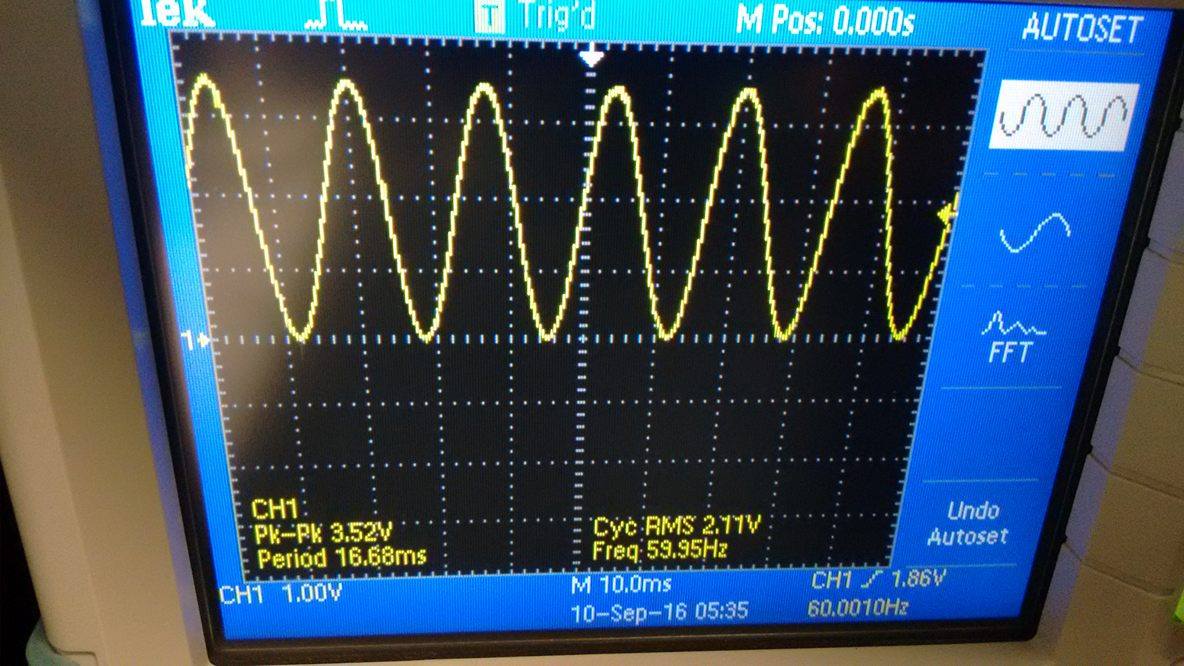
Fig 4: SPWM output without filtering (without dead band, frequency showing 30.3176)
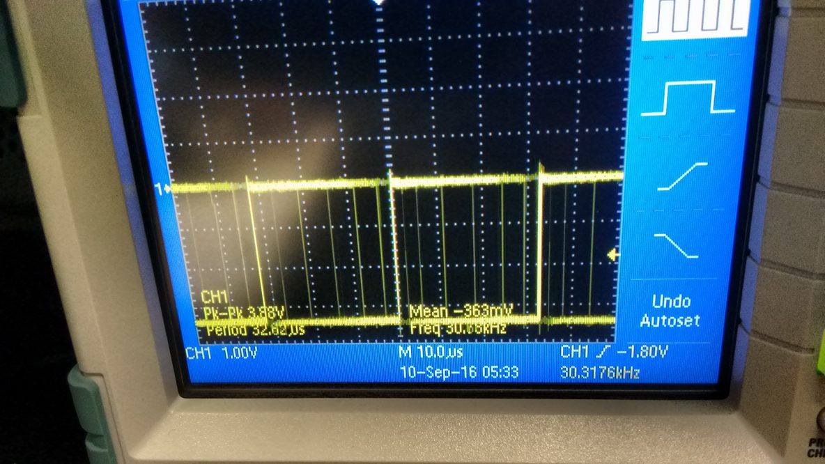
Fig 5: Code when I did not use dead band
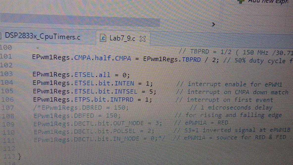
Fig 6: Error after debugging