This thread has been locked.

If you have a related question, please click the "Ask a related question" button in the top right corner. The newly created question will be automatically linked to this question.

high Rover_L value

Other Parts Discussed in Thread: MOTORWARE, DRV8312, DRV8303, DRV8301

Kit: DRV8312EVM Rev D
GUI:Instaspin-FOC Motorware Instrumentation

Control card: F2802 (Piccolo A)

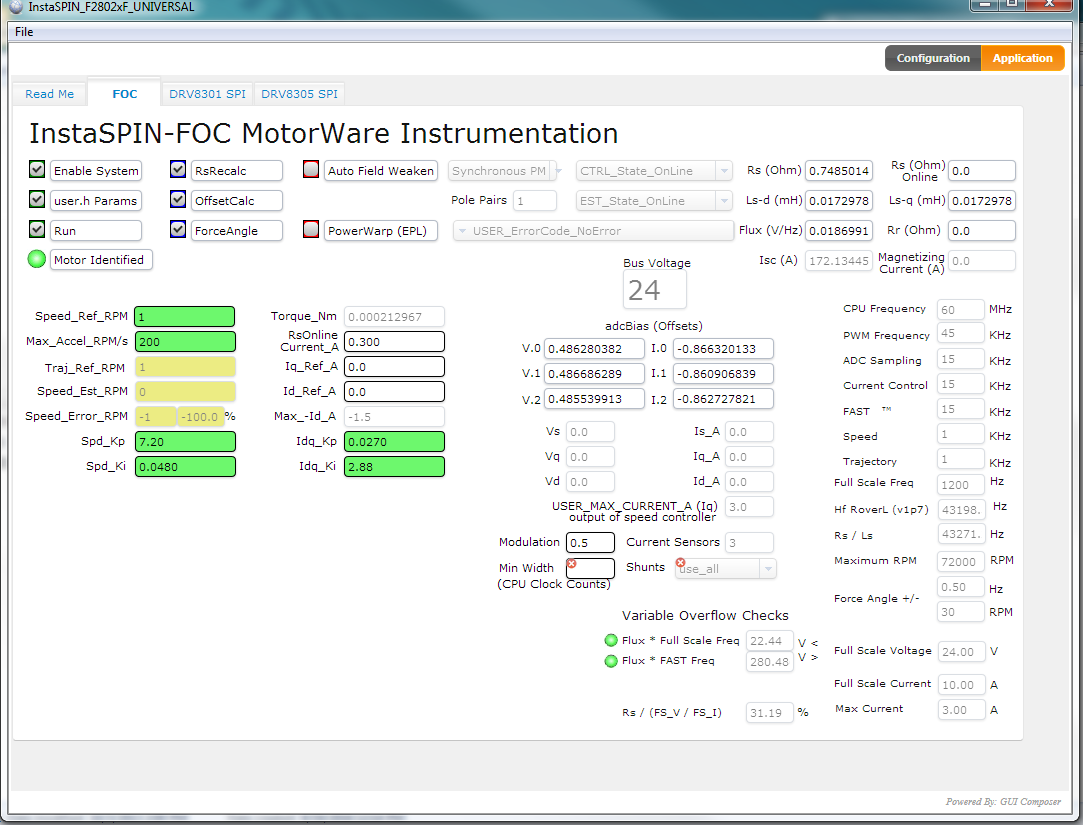
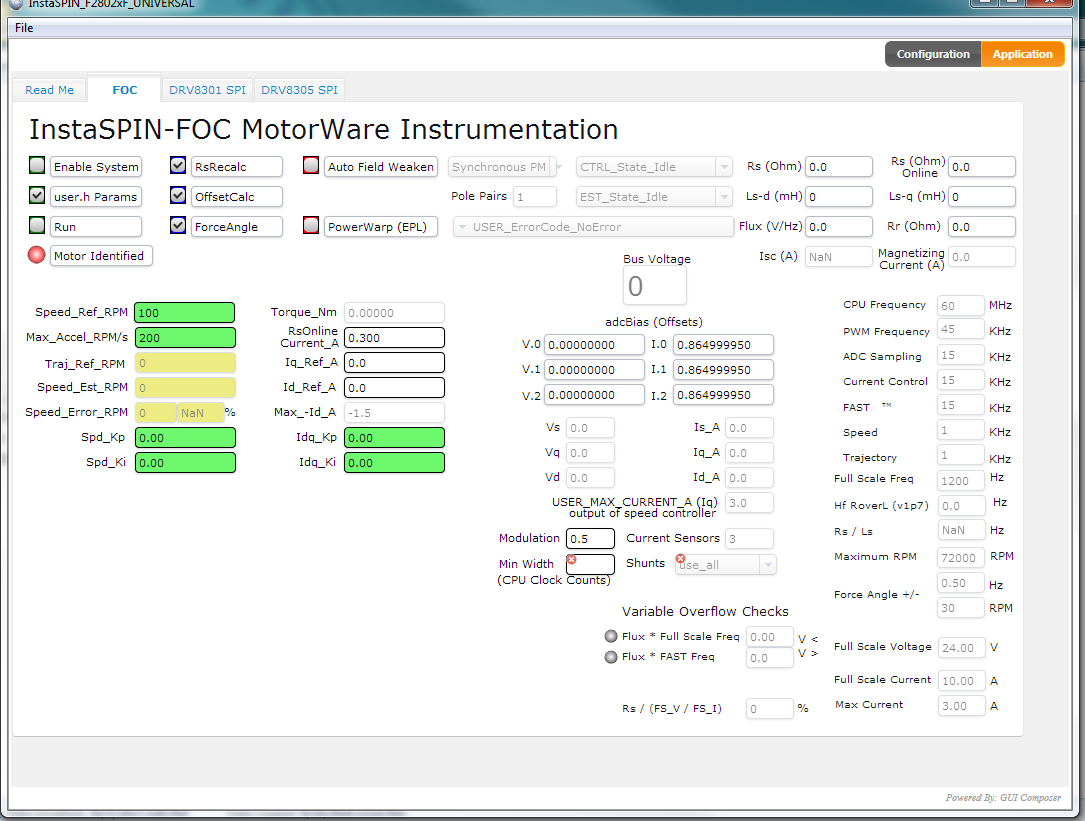
I want to run a 24 V  30K rpm bldc motor .I tried ID using program 5b,but during identification the RoverL is always equal to 2000.
And the motor sanity check failed for Rs/Ls.
according to GUI Quick Start guide Instaspin Universal ,I tried to attempt ID using lab 2c but still RoverL came around 12000.
The USER_R_OVER_L_EST_FREQ_Hz is already set at  300.

How should I go further ? Please help

  • RoverL of 12000 is valid.
    using proj_lab02c to the ID process complete? did the motor start-up and keep spinning during the ID process?

    you are following the best guide

    attach your user.h if you like
  • also
    "The USER_R_OVER_L_EST_FREQ_Hz is already set at 300."

    USER_R_OVER_L_EST_FREQ_Hz is the frequency of the injected signal during RoverL test. It isn't related to the RoverL of the motor that is returned from the test.
  • #ifndef _USER_H_
    #define _USER_H_
    /* --COPYRIGHT--,BSD
     * Copyright (c) 2012, Texas Instruments Incorporated
     * All rights reserved.
     *
     * Redistribution and use in source and binary forms, with or without
     * modification, are permitted provided that the following conditions
     * are met:
     *
     * *  Redistributions of source code must retain the above copyright
     *    notice, this list of conditions and the following disclaimer.
     *
     * *  Redistributions in binary form must reproduce the above copyright
     *    notice, this list of conditions and the following disclaimer in the
     *    documentation and/or other materials provided with the distribution.
     *
     * *  Neither the name of Texas Instruments Incorporated nor the names of
     *    its contributors may be used to endorse or promote products derived
     *    from this software without specific prior written permission.
     *
     * THIS SOFTWARE IS PROVIDED BY THE COPYRIGHT HOLDERS AND CONTRIBUTORS "AS IS"
     * AND ANY EXPRESS OR IMPLIED WARRANTIES, INCLUDING, BUT NOT LIMITED TO,
     * THE IMPLIED WARRANTIES OF MERCHANTABILITY AND FITNESS FOR A PARTICULAR
     * PURPOSE ARE DISCLAIMED. IN NO EVENT SHALL THE COPYRIGHT OWNER OR
     * CONTRIBUTORS BE LIABLE FOR ANY DIRECT, INDIRECT, INCIDENTAL, SPECIAL,
     * EXEMPLARY, OR CONSEQUENTIAL DAMAGES (INCLUDING, BUT NOT LIMITED TO,
     * PROCUREMENT OF SUBSTITUTE GOODS OR SERVICES; LOSS OF USE, DATA, OR PROFITS;
     * OR BUSINESS INTERRUPTION) HOWEVER CAUSED AND ON ANY THEORY OF LIABILITY,
     * WHETHER IN CONTRACT, STRICT LIABILITY, OR TORT (INCLUDING NEGLIGENCE OR
     * OTHERWISE) ARISING IN ANY WAY OUT OF THE USE OF THIS SOFTWARE,
     * EVEN IF ADVISED OF THE POSSIBILITY OF SUCH DAMAGE.
     * --/COPYRIGHT--*/
    
    //! \file   solutions/instaspin_foc/boards/drv8312kit_revD/f28x/f2802xF/src/user.h
    //! \brief  Contains the public interface for user initialization data for the CTRL, HAL, and EST modules 
    //!
    //! (C) Copyright 2012, Texas Instruments, Inc.
    
    
    // **************************************************************************
    // the includes
    
    // modules
    #include "sw/modules/types/src/types.h"
    #include "sw/modules/motor/src/32b/motor.h"
    #include "sw/modules/est/src/32b/est.h"
    #include "sw/modules/est/src/est_states.h"
    #include "sw/modules/est/src/est_Flux_states.h"
    #include "sw/modules/est/src/est_Ls_states.h"
    #include "sw/modules/est/src/est_Rs_states.h"
    #include "sw/modules/ctrl/src/32b/ctrl_obj.h"
    
    
    // platforms
    #include "sw/modules/fast/src/32b/userParams.h"
    
    //!
    //!
    //! \defgroup USER USER
    //!
    //@{
    
    
    #ifdef __cplusplus
    extern "C" {
    #endif
    
    // **************************************************************************
    // the defines
    
    
    //! \brief CURRENTS AND VOLTAGES
    // **************************************************************************
    //! \brief Defines the full scale frequency for IQ variable, Hz
    //! \brief All frequencies are converted into (pu) based on the ratio to this value
    //! \brief this value MUST be larger than the maximum speed that you are expecting from the motor 
    #define USER_IQ_FULL_SCALE_FREQ_Hz        (600.0)   // 800 Example with buffer for 8-pole 6 KRPM motor to be run to 10 KRPM with field weakening; Hz =(RPM * Poles) / 120
    
    //! \brief Defines full scale value for the IQ30 variable of Voltage inside the system
    //! \brief All voltages are converted into (pu) based on the ratio to this value
    //! \brief WARNING: this value MUST meet the following condition: USER_IQ_FULL_SCALE_VOLTAGE_V > 0.5 * USER_MOTOR_MAX_CURRENT * USER_MOTOR_Ls_d * USER_VOLTAGE_FILTER_POLE_rps, 
    //! \brief WARNING: otherwise the value can saturate and roll-over, causing an inaccurate value
    //! \brief WARNING: this value is OFTEN greater than the maximum measured ADC value, especially with high Bemf motors operating at higher than rated speeds
    //! \brief WARNING: if you know the value of your Bemf constant, and you know you are operating at a multiple speed due to field weakening, be sure to set this value higher than the expected Bemf voltage
    //! \brief It is recommended to start with a value ~3x greater than the USER_ADC_FULL_SCALE_VOLTAGE_V and increase to 4-5x if scenarios where a Bemf calculation may exceed these limits
    //! \brief This value is also used to calculate the minimum flux value: USER_IQ_FULL_SCALE_VOLTAGE_V/USER_EST_FREQ_Hz/0.7
    #define USER_IQ_FULL_SCALE_VOLTAGE_V      (22.0)   // 24.0 Example for drv8312_revd typical usage and the Anaheim motor
    
    //! \brief Defines the maximum voltage at the input to the AD converter
    //! \brief The value that will be represented by the maximum ADC input (3.3V) and conversion (0FFFh)
    //! \brief Hardware dependent, this should be based on the voltage sensing and scaling to the ADC input
    #define USER_ADC_FULL_SCALE_VOLTAGE_V       (66.32)      // 66.32 drv8312_revd voltage scaling
    
    //! \brief Defines the voltage scale factor for the system
    //! \brief Compile time calculation for scale factor (ratio) used throughout the system
    #define USER_VOLTAGE_SF               ((float_t)((USER_ADC_FULL_SCALE_VOLTAGE_V)/(USER_IQ_FULL_SCALE_VOLTAGE_V)))
    
    //! \brief Defines the full scale current for the IQ variables, A
    //! \brief All currents are converted into (pu) based on the ratio to this value
    //! \brief WARNING: this value MUST be larger than the maximum current readings that you are expecting from the motor or the reading will roll over to 0, creating a control issue 
    #define USER_IQ_FULL_SCALE_CURRENT_A          (10.0)   // 10.0 Example for drv8312_revd typical usage
    
    //! \brief Defines the maximum current at the AD converter
    //! \brief The value that will be represented by the maximum ADC input (3.3V) and conversion (0FFFh)
    //! \brief Hardware dependent, this should be based on the current sensing and scaling to the ADC input
    #define USER_ADC_FULL_SCALE_CURRENT_A        (17.30)     // 17.30 drv8312_revd current scaling
    
    //! \brief Defines the current scale factor for the system
    //! \brief Compile time calculation for scale factor (ratio) used throughout the system
    #define USER_CURRENT_SF               ((float_t)((USER_ADC_FULL_SCALE_CURRENT_A)/(USER_IQ_FULL_SCALE_CURRENT_A)))
    
    //! \brief Defines the number of current sensors used
    //! \brief Defined by the hardware capability present
    //! \brief May be (2) or (3)
    #define USER_NUM_CURRENT_SENSORS            (3)   // 3 Preferred setting for best performance across full speed range, allows for 100% duty cycle
    
    //! \brief Defines the number of voltage (phase) sensors
    //! \brief Must be (3)
    #define USER_NUM_VOLTAGE_SENSORS            (3) // 3 Required
    
    //! \brief ADC current offsets for A, B, and C phases
    //! \brief One-time hardware dependent, though the calibration can be done at run-time as well
    //! \brief After initial board calibration these values should be updated for your specific hardware so they are available after compile in the binary to be loaded to the controller
    #define   I_A_offset    (-0.869157374)
    #define   I_B_offset    (-0.863976419)
    #define   I_C_offset    (-0.865477204)
    
    //! \brief ADC voltage offsets for A, B, and C phases
    //! \brief One-time hardware dependent, though the calibration can be done at run-time as well
    //! \brief After initial board calibration these values should be updated for your specific hardware so they are available after compile in the binary to be loaded to the controller
    #define   V_A_offset    (2.00761110)
    #define   V_B_offset    (0.691368520)
    #define   V_C_offset    (0.690536439)
    
    
    //! \brief CLOCKS & TIMERS
    // **************************************************************************
    //! \brief Defines the system clock frequency, MHz
    #define USER_SYSTEM_FREQ_MHz             (60.0)
    
    //! \brief Defines the Pulse Width Modulation (PWM) frequency, kHz
    //! \brief PWM frequency can be set directly here up to 30 KHz safely (60 KHz MAX in some cases)
    //! \brief For higher PWM frequencies (60 KHz+ typical for low inductance, high current ripple motors) it is recommended to use the ePWM hardware
    //! \brief and adjustable ADC SOC to decimate the ADC conversion done interrupt to the control system, or to use the software Que example.
    //! \brief Otherwise you risk missing interrupts and disrupting the timing of the control state machine
    #define USER_PWM_FREQ_kHz                (60.0) //30.0 Example, 8.0 - 30.0 KHz typical; 45-80 KHz may be required for very low inductance, high speed motors
    
    //! \brief Defines the maximum Voltage vector (Vs) magnitude allowed.  This value sets the maximum magnitude for the output of the
    //! \brief Id and Iq PI current controllers.  The Id and Iq current controller outputs are Vd and Vq.
    //! \brief The relationship between Vs, Vd, and Vq is:  Vs = sqrt(Vd^2 + Vq^2).  In this FOC controller, the
    //! \brief Vd value is set equal to USER_MAX_VS_MAG*USER_VD_MAG_FACTOR.  Vq = sqrt(USER_MAX_VS_MAG^2 - Vd^2).
    //! \brief Set USER_MAX_VS_MAG = 0.5 for a pure sinewave with a peak at SQRT(3)/2 = 86.6% duty cycle.  No current reconstruction is needed for this scenario.
    //! \brief Set USER_MAX_VS_MAG = 1/SQRT(3) = 0.5774 for a pure sinewave with a peak at 100% duty cycle.  Current reconstruction will be needed for this scenario (Lab10a-x).
    //! \brief Set USER_MAX_VS_MAG = 2/3 = 0.6666 to create a trapezoidal voltage waveform.  Current reconstruction will be needed for this scenario (Lab10a-x).
    //! \brief For space vector over-modulation, see lab 10 for details on system requirements that will allow the SVM generator to go all the way to trapezoidal.
    #define USER_MAX_VS_MAG_PU        (0.5)    // Set to 0.5 if a current reconstruction technique is not used.  Look at the module svgen_current in lab10a-x for more info.
    
    //! \brief Defines the address of estimator handle
    //!
    #define USER_EST_HANDLE_ADDRESS    (0x600)
    
    //! \brief Defines the direct voltage (Vd) scale factor
    //!
    #define USER_VD_SF                 (0.95)
    
    //! \brief Defines the Pulse Width Modulation (PWM) period, usec
    //! \brief Compile time calculation
    #define USER_PWM_PERIOD_usec       (1000.0/USER_PWM_FREQ_kHz)
    
    //! \brief Defines the Interrupt Service Routine (ISR) frequency, Hz
    //!
    #define USER_ISR_FREQ_Hz           ((float_t)USER_PWM_FREQ_kHz * 1000.0 / (float_t)USER_NUM_PWM_TICKS_PER_ISR_TICK)
    
    //! \brief Defines the Interrupt Service Routine (ISR) period, usec
    //!
    #define USER_ISR_PERIOD_usec       (USER_PWM_PERIOD_usec * (float_t)USER_NUM_PWM_TICKS_PER_ISR_TICK)
    
    
    //! \brief DECIMATION
    // **************************************************************************
    //! \brief Defines the number of pwm clock ticks per isr clock tick
    //!        Note: Valid values are 1, 2 or 3 only
    #define USER_NUM_PWM_TICKS_PER_ISR_TICK        (3)
    
    //! \brief Defines the number of isr ticks (hardware) per controller clock tick (software)
    //! \brief Controller clock tick (CTRL) is the main clock used for all timing in the software
    //! \brief Typically the PWM Frequency triggers (can be decimated by the ePWM hardware for less overhead) an ADC SOC
    //! \brief ADC SOC triggers an ADC Conversion Done
    //! \brief ADC Conversion Done triggers ISR
    //! \brief This relates the hardware ISR rate to the software controller rate
    //! \brief Typcially want to consider some form of decimation (ePWM hardware, CURRENT or EST) over 16KHz ISR to insure interrupt completes and leaves time for background tasks
    #define USER_NUM_ISR_TICKS_PER_CTRL_TICK       (1)      // 2 Example, controller clock rate (CTRL) runs at PWM / 2; ex 30 KHz PWM, 15 KHz control
    
    //! \brief Defines the number of controller clock ticks per current controller clock tick
    //! \brief Relationship of controller clock rate to current controller (FOC) rate
    #define USER_NUM_CTRL_TICKS_PER_CURRENT_TICK   (1)      // 1 Typical, Forward FOC current controller (Iq/Id/IPARK/SVPWM) runs at same rate as CTRL. 
    
    //! \brief Defines the number of controller clock ticks per estimator clock tick
    //! \brief Relationship of controller clock rate to estimator (FAST) rate
    //! \brief Depends on needed dynamic performance, FAST provides very good results as low as 1 KHz while more dynamic or high speed applications may require up to 15 KHz
    #define USER_NUM_CTRL_TICKS_PER_EST_TICK       (1)      // 1 Typical, FAST estimator runs at same rate as CTRL;
    
    //! \brief Defines the number of controller clock ticks per speed controller clock tick
    //! \brief Relationship of controller clock rate to speed loop rate
    #define USER_NUM_CTRL_TICKS_PER_SPEED_TICK  (15)   // 15 Typical to match PWM, ex: 15KHz PWM, controller, and current loop, 1KHz speed loop
    
    //! \brief Defines the number of controller clock ticks per trajectory clock tick
    //! \brief Relationship of controller clock rate to trajectory loop rate
    //! \brief Typically the same as the speed rate
    #define USER_NUM_CTRL_TICKS_PER_TRAJ_TICK   (15)   // 15 Typical to match PWM, ex: 10KHz controller & current loop, 1KHz speed loop, 1 KHz Trajectory
    
    //! \brief Defines the controller frequency, Hz
    //! \brief Compile time calculation
    #define USER_CTRL_FREQ_Hz          (uint_least32_t)(USER_ISR_FREQ_Hz/USER_NUM_ISR_TICKS_PER_CTRL_TICK)
    
    //! \brief Defines the estimator frequency, Hz
    //! \brief Compile time calculation
    #define USER_EST_FREQ_Hz           (uint_least32_t)(USER_CTRL_FREQ_Hz/USER_NUM_CTRL_TICKS_PER_EST_TICK)
    
    //! \brief Defines the trajectory frequency, Hz
    //! \brief Compile time calculation
    #define USER_TRAJ_FREQ_Hz          (uint_least32_t)(USER_CTRL_FREQ_Hz/USER_NUM_CTRL_TICKS_PER_TRAJ_TICK)
    
    //! \brief Defines the controller execution period, usec
    //! \brief Compile time calculation
    #define USER_CTRL_PERIOD_usec      (USER_ISR_PERIOD_usec * USER_NUM_ISR_TICKS_PER_CTRL_TICK)
    
    //! \brief Defines the controller execution period, sec
    //! \brief Compile time calculation
    #define USER_CTRL_PERIOD_sec       ((float_t)USER_CTRL_PERIOD_usec/(float_t)1000000.0)
    
    
    //! \brief LIMITS
    // **************************************************************************
    //! \brief Defines the maximum negative current to be applied in Id reference
    //! \brief Used in field weakening only, this is a safety setting (e.g. to protect against demagnetization)
    //! \brief User must also be aware that overall current magnitude [sqrt(Id^2 + Iq^2)] should be kept below any machine design specifications
    #define USER_MAX_NEGATIVE_ID_REF_CURRENT_A     (-0.5 * USER_MOTOR_MAX_CURRENT)   // -0.5 * USER_MOTOR_MAX_CURRENT Example, adjust to meet safety needs of your motor
    
    //! \brief Defines the low speed limit for the flux integrator, pu 
    //! \brief This is the speed range (CW/CCW) at which the ForceAngle object is active, but only if Enabled
    //! \brief Outside of this speed - or if Disabled - the ForcAngle will NEVER be active and the angle is provided by FAST only
    #define USER_ZEROSPEEDLIMIT   (0.5 / USER_IQ_FULL_SCALE_FREQ_Hz)     // 0.002 pu, 1-5 Hz typical; Hz = USER_ZEROSPEEDLIMIT * USER_IQ_FULL_SCALE_FREQ_Hz
    
    //! \brief Defines the force angle frequency, Hz
    //! \brief Frequency of stator vector rotation used by the ForceAngle object
    //! \brief Can be positive or negative
    #define USER_FORCE_ANGLE_FREQ_Hz   (2.0 * USER_ZEROSPEEDLIMIT * USER_IQ_FULL_SCALE_FREQ_Hz)      // 1.0 Typical force angle start-up speed
    
    //! \brief Defines the maximum current slope for Id trajectory during PowerWarp
    //! \brief For Induction motors only, controls how fast Id input can change under PowerWarp control
    #define USER_MAX_CURRENT_SLOPE_POWERWARP   (0.3*USER_MOTOR_RES_EST_CURRENT/USER_IQ_FULL_SCALE_CURRENT_A/USER_TRAJ_FREQ_Hz)  // 0.3*RES_EST_CURRENT / IQ_FULL_SCALE_CURRENT / TRAJ_FREQ Typical to produce 1-sec rampup/down
    
    //! \brief Defines the starting maximum acceleration AND deceleration for the speed profiles, Hz/s
    //! \brief Updated in run-time through user functions
    //! \brief Inverter, motor, inertia, and load will limit actual acceleration capability
    #define USER_MAX_ACCEL_Hzps                 (20.0)      // 20.0 Default
    
    //! \brief Defines maximum acceleration for the estimation speed profiles, Hz/s
    //! \brief Only used during Motor ID (commission)
    #define USER_MAX_ACCEL_EST_Hzps           (10.0)         // 5.0 Default, don't change
    
    //! \brief Defines the maximum current slope for Id trajectory during estimation
    #define USER_MAX_CURRENT_SLOPE           (USER_MOTOR_RES_EST_CURRENT/USER_IQ_FULL_SCALE_CURRENT_A/USER_TRAJ_FREQ_Hz)      // USER_MOTOR_RES_EST_CURRENT/USER_IQ_FULL_SCALE_CURRENT_A/USER_TRAJ_FREQ_Hz Default, don't change
    
    //! \brief Defines the fraction of IdRated to use during rated flux estimation
    //!
    #define USER_IDRATED_FRACTION_FOR_RATED_FLUX (1.0)      // 1.0 Default, don't change
    
    //! \brief Defines the fraction of IdRated to use during inductance estimation
    //!
    #define USER_IDRATED_FRACTION_FOR_L_IDENT    (1.0)      // 1.0 Default, don't change
    
    //! \brief Defines the IdRated delta to use during estimation
    //!
    #define USER_IDRATED_DELTA                  (0.00002)
    
    //! \brief Defines the fraction of SpeedMax to use during inductance estimation
    //!
    #define USER_SPEEDMAX_FRACTION_FOR_L_IDENT  (1.0)      // 1.0 Default, don't change
    
    //! \brief Defines flux fraction to use during inductance identification
    //!
    #define USER_FLUX_FRACTION           (1.0)            // 1.0 Default, don't change
    
    //! \brief Defines the PowerWarp gain for computing Id reference
    //! \brief Induction motors only
    #define USER_POWERWARP_GAIN                   (1.0)         // 1.0 Default, don't change
    
    //! \brief Defines the R/L estimation frequency, Hz
    //! \brief User higher values for low inductance motors and lower values for higher inductance
    //! \brief motors.  The values can range from 100 to 300 Hz.
    #define USER_R_OVER_L_EST_FREQ_Hz (300)               // 300 Default
    
    
    //! \brief POLES
    // **************************************************************************
    //! \brief Defines the analog voltage filter pole location, Hz
    //! \brief Must match the hardware filter for Vph
    #define USER_VOLTAGE_FILTER_POLE_Hz  (714.14)   // 714.14, value for drv8312_revd hardware
    
    //! \brief Defines the analog voltage filter pole location, rad/s
    //! \brief Compile time calculation from Hz to rad/s
    #define USER_VOLTAGE_FILTER_POLE_rps  (2.0 * MATH_PI * USER_VOLTAGE_FILTER_POLE_Hz)
    
    //! \brief Defines the software pole location for the voltage and current offset estimation, rad/s
    //! \brief Should not be changed from default of (20.0)
    #define USER_OFFSET_POLE_rps            (20.0)   // 20.0 Default, do not change
    
    //! \brief Defines the software pole location for the flux estimation, rad/s
    //! \brief Should not be changed from default of (100.0)
    #define USER_FLUX_POLE_rps              (100.0)   // 100.0 Default, do not change
    
    //! \brief Defines the software pole location for the direction filter, rad/s
    #define USER_DIRECTION_POLE_rps             (6.0)   // 6.0 Default, do not change
    
    //! \brief Defines the software pole location for the speed control filter, rad/s
    #define USER_SPEED_POLE_rps           (100.0)   // 100.0 Default, do not change
    
    //! \brief Defines the software pole location for the DC bus filter, rad/s
    #define USER_DCBUS_POLE_rps           (100.0)   // 100.0 Default, do not change
    
    //! \brief Defines the convergence factor for the estimator
    //! \brief Do not change from default for FAST
    #define   USER_EST_KAPPAQ               (1.5)   // 1.5 Default, do not change
    
    // **************************************************************************
    // end the defines
    
    
    //! \brief USER MOTOR & ID SETTINGS
    // **************************************************************************
    
    //! \brief Define each motor with a unique name and ID number
    // BLDC & SMPM motors
    #define Estun_EMJ_04APB22           101
    #define My_motor        		     102
    #define teknic_2310P                108
    
    // IPM motors
    // If user provides separate Ls-d, Ls-q
    // else treat as SPM with user or identified average Ls
    #define Belt_Drive_Washer_IPM       201
    
    // ACIM motors
    #define Marathon_5K33GN2A           301
    
    //! \brief Uncomment the motor which should be included at compile
    //! \brief These motor ID settings and motor parameters are then available to be used by the control system
    //! \brief Once your ideal settings and parameters are identified update the motor section here so it is available in the binary code
    //#define USER_MOTOR Estun_EMJ_04APB22
    #define USER_MOTOR My_motor
    //#define USER_MOTOR My_Motor
    //#define USER_MOTOR Belt_Drive_Washer_IPM
    //#define USER_MOTOR Marathon_5K33GN2A
    //#define USER_MOTOR teknic_2310P
    
    
    #if (USER_MOTOR == Estun_EMJ_04APB22)                  // Name must match the motor #define
    #define USER_MOTOR_TYPE                 MOTOR_Type_Pm  // Motor_Type_Pm (All Synchronous: BLDC, PMSM, SMPM, IPM) or Motor_Type_Induction (Asynchronous ACI)
    #define USER_MOTOR_NUM_POLE_PAIRS       (4)            // PAIRS, not total poles. Used to calculate user RPM from rotor Hz only
    #define USER_MOTOR_Rr                   (NULL)         // Induction motors only, else NULL
    #define USER_MOTOR_Rs                   (2.303403)     // Identified phase to neutral resistance in a Y equivalent circuit (Ohms, float)
    #define USER_MOTOR_Ls_d                 (0.008464367)  // For PM, Identified average stator inductance  (Henry, float)
    #define USER_MOTOR_Ls_q                 (0.008464367)  // For PM, Identified average stator inductance  (Henry, float)
    #define USER_MOTOR_RATED_FLUX           (0.38)         // Identified TOTAL flux linkage between the rotor and the stator (V/Hz)
    #define USER_MOTOR_MAGNETIZING_CURRENT  (NULL)         // Induction motors only, else NULL
    #define USER_MOTOR_RES_EST_CURRENT      (0.3)          // During Motor ID, maximum current (Amperes, float) used for Rs estimation, 10-20% rated current
    #define USER_MOTOR_IND_EST_CURRENT      (-0.3)         // During Motor ID, maximum current (negative Amperes, float) used for Ls estimation, use just enough to enable rotation
    #define USER_MOTOR_MAX_CURRENT          (3.82)         // CRITICAL: Used during ID and run-time, sets a limit on the maximum current command output of the provided Speed PI Controller to the Iq controller
    #define USER_MOTOR_FLUX_EST_FREQ_Hz     (20.0)         // During Motor ID, maximum commanded speed (Hz, float), ~10% rated
    
    #elif (USER_MOTOR == My_motor)
    #define USER_MOTOR_TYPE                 MOTOR_Type_Pm
    #define USER_MOTOR_NUM_POLE_PAIRS       (1)
    #define USER_MOTOR_Rr                   (NULL)
    #define USER_MOTOR_Rs                   (0.5355010032)
    #define USER_MOTOR_Ls_d                 (0.0001393029)
    #define USER_MOTOR_Ls_q                 (0.0001393029)
    #define USER_MOTOR_RATED_FLUX           (0.010713812)
    #define USER_MOTOR_MAGNETIZING_CURRENT  (NULL)
    #define USER_MOTOR_RES_EST_CURRENT      (0.2)
    #define USER_MOTOR_IND_EST_CURRENT      (-0.2)
    #define USER_MOTOR_MAX_CURRENT          (2.0)
    #define USER_MOTOR_FLUX_EST_FREQ_Hz     (80.0)//80


    #elif (USER_MOTOR == Belt_Drive_Washer_IPM)
    #define USER_MOTOR_TYPE                 MOTOR_Type_Pm
    #define USER_MOTOR_NUM_POLE_PAIRS       (4)
    #define USER_MOTOR_Rr                   (NULL)
    #define USER_MOTOR_Rs                   (2.832002)
    #define USER_MOTOR_Ls_d                 (0.0115)
    #define USER_MOTOR_Ls_q                 (0.0135)
    #define USER_MOTOR_RATED_FLUX           (0.5022156)
    #define USER_MOTOR_MAGNETIZING_CURRENT  (NULL)
    #define USER_MOTOR_RES_EST_CURRENT      (1.0)
    #define USER_MOTOR_IND_EST_CURRENT      (-1.0)
    #define USER_MOTOR_MAX_CURRENT          (4.0)
    #define USER_MOTOR_FLUX_EST_FREQ_Hz     (20.0)
    
    #elif (USER_MOTOR == Marathon_5K33GN2A)                      // Name must match the motor #define
    #define USER_MOTOR_TYPE                 MOTOR_Type_Induction // Motor_Type_Pm (All Synchronous: BLDC, PMSM, SMPM, IPM) or Motor_Type_Induction (Asynchronous ACI)
    #define USER_MOTOR_NUM_POLE_PAIRS       (2)                  // PAIRS, not total poles. Used to calculate user RPM from rotor Hz only
    #define USER_MOTOR_Rr                   (5.508003)           // Identified phase to neutral in a Y equivalent circuit (Ohms, float)
    #define USER_MOTOR_Rs                   (10.71121)           // Identified phase to neutral in a Y equivalent circuit (Ohms, float)
    #define USER_MOTOR_Ls_d                 (0.05296588)         // For Induction, Identified average stator inductance  (Henry, float)
    #define USER_MOTOR_Ls_q                 (0.05296588)         // For Induction, Identified average stator inductance  (Henry, float)
    #define USER_MOTOR_RATED_FLUX           (0.8165*220.0/60.0)  // sqrt(2/3)* Rated V (line-line) / Rated Freq (Hz)
    #define USER_MOTOR_MAGNETIZING_CURRENT  (1.378)              // Identified magnetizing current for induction motors, else NULL
    #define USER_MOTOR_RES_EST_CURRENT      (0.5)                // During Motor ID, maximum current (Amperes, float) used for Rs estimation, 10-20% rated current
    #define USER_MOTOR_IND_EST_CURRENT      (NULL)               // not used for induction
    #define USER_MOTOR_MAX_CURRENT          (2.0)                // CRITICAL: Used during ID and run-time, sets a limit on the maximum current command output of the provided Speed PI Controller to the Iq controller
    #define USER_MOTOR_FLUX_EST_FREQ_Hz     (5.0)                // During Motor ID, maximum commanded speed (Hz, float). Should always use 5 Hz for Induction.
    
    
    #else
    #error No motor type specified
    #endif
    
    #ifndef USER_MOTOR
    #error Motor is not defined in user.h
    #endif
    
    #ifndef USER_MOTOR_TYPE
    #error The motor type is not defined in user.h
    #endif
    
    #ifndef USER_MOTOR_NUM_POLE_PAIRS
    #error Number of motor pole pairs is not defined in user.h
    #endif
    
    #ifndef USER_MOTOR_Rr
    #error The rotor resistance is not defined in user.h
    #endif
    
    #ifndef USER_MOTOR_Rs
    #error The stator resistance is not defined in user.h
    #endif
    
    #ifndef USER_MOTOR_Ls_d
    #error The direct stator inductance is not defined in user.h
    #endif
    
    #ifndef USER_MOTOR_Ls_q
    #error The quadrature stator inductance is not defined in user.h
    #endif
    
    #ifndef USER_MOTOR_RATED_FLUX
    #error The rated flux of motor is not defined in user.h
    #endif
    
    #ifndef USER_MOTOR_MAGNETIZING_CURRENT
    #error The magnetizing current is not defined in user.h
    #endif
    
    #ifndef USER_MOTOR_RES_EST_CURRENT
    #error The resistance estimation current is not defined in user.h
    #endif
    
    #ifndef USER_MOTOR_IND_EST_CURRENT
    #error The inductance estimation current is not defined in user.h
    #endif
    
    #ifndef USER_MOTOR_MAX_CURRENT
    #error The maximum current is not defined in user.h
    #endif
    
    #ifndef USER_MOTOR_FLUX_EST_FREQ_Hz
    #error The flux estimation frequency is not defined in user.h
    #endif
    
    
    // **************************************************************************
    // the functions
    
    
    //! \brief      Sets the user parameter values
    //! \param[in]  pUserParams  The pointer to the user param structure
    extern void USER_setParams(USER_Params *pUserParams);
    
    
    //! \brief      Checks for errors in the user parameter values
    //! \param[in]  pUserParams  The pointer to the user param structure
    extern void USER_checkForErrors(USER_Params *pUserParams);
    
    
    //! \brief      Gets the error code in the user parameters
    //! \param[in]  pUserParams  The pointer to the user param structure
    //! \return     The error code
    extern USER_ErrorCode_e USER_getErrorCode(USER_Params *pUserParams);
    
    
    //! \brief      Sets the error code in the user parameters
    //! \param[in]  pUserParams  The pointer to the user param structure
    //! \param[in]  errorCode    The error code
    extern void USER_setErrorCode(USER_Params *pUserParams,const USER_ErrorCode_e errorCode);
    
    
    //! \brief      Recalculates Inductances with the correct Q Format
    //! \param[in]  handle       The controller (CTRL) handle
    extern void USER_softwareUpdate1p6(CTRL_Handle handle);
    
    
    //! \brief      Updates Id and Iq PI gains
    //! \param[in]  handle       The controller (CTRL) handle
    extern void USER_calcPIgains(CTRL_Handle handle);
    
    
    //! \brief      Computes the scale factor needed to convert from torque created by Ld, Lq, Id and Iq, from per unit to Nm
    //! \return     The scale factor to convert torque from (Ld - Lq) * Id * Iq from per unit to Nm, in IQ24 format
    extern _iq USER_computeTorque_Ls_Id_Iq_pu_to_Nm_sf(void);
    
    
    //! \brief      Computes the scale factor needed to convert from torque created by flux and Iq, from per unit to Nm
    //! \return     The scale factor to convert torque from Flux * Iq from per unit to Nm, in IQ24 format
    extern _iq USER_computeTorque_Flux_Iq_pu_to_Nm_sf(void);
    
    
    //! \brief      Computes the scale factor needed to convert from per unit to Wb
    //! \return     The scale factor to convert from flux per unit to flux in Wb, in IQ24 format
    extern _iq USER_computeFlux_pu_to_Wb_sf(void);
    
    
    //! \brief      Computes the scale factor needed to convert from per unit to V/Hz
    //! \return     The scale factor to convert from flux per unit to flux in V/Hz, in IQ24 format
    extern _iq USER_computeFlux_pu_to_VpHz_sf(void);
    
    
    //! \brief      Computes Flux in Wb or V/Hz depending on the scale factor sent as parameter
    //! \param[in]  handle       The controller (CTRL) handle
    //! \param[in]  sf           The scale factor to convert flux from per unit to Wb or V/Hz
    //! \return     The flux in Wb or V/Hz depending on the scale factor sent as parameter, in IQ24 format
    extern _iq USER_computeFlux(CTRL_Handle handle, const _iq sf);
    
    
    //! \brief      Computes Torque in Nm
    //! \param[in]  handle          The controller (CTRL) handle
    //! \param[in]  torque_Flux_sf  The scale factor to convert torque from (Ld - Lq) * Id * Iq from per unit to Nm
    //! \param[in]  torque_Ls_sf    The scale factor to convert torque from Flux * Iq from per unit to Nm
    //! \return     The torque in Nm, in IQ24 format
    extern _iq USER_computeTorque_Nm(CTRL_Handle handle, const _iq torque_Flux_sf, const _iq torque_Ls_sf);
    
    
    //! \brief      Computes Torque in lbin
    //! \param[in]  handle          The controller (CTRL) handle
    //! \param[in]  torque_Flux_sf  The scale factor to convert torque from (Ld - Lq) * Id * Iq from per unit to lbin
    //! \param[in]  torque_Ls_sf    The scale factor to convert torque from Flux * Iq from per unit to lbin
    //! \return     The torque in lbin, in IQ24 format
    extern _iq USER_computeTorque_lbin(CTRL_Handle handle, const _iq torque_Flux_sf, const _iq torque_Ls_sf);
    
    
    #ifdef __cplusplus
    }
    #endif // extern "C"
    
    //@} // ingroup
    #endif // end of _USER_H_ definition
    
    
     The motor  stops for 2-3  seconds when switching from Ramp_on to Rated flux ,but it starts running  again till Idle.I tried  increasing USER_MOTOR_FLUX_EST_FREQ_HZ and reducing the USER_IQ_FULL_SCALE_VOLTAGE_V but still it stops for  while and runs again.

    Seems due to increasing USER_MOTOR_FLUX_EST_FREQ_Hz ,the ramp up  times out.But  after increasing the USER_MAX_ACCEL_EST_Hzps  the motor stops while switching to Rated flux. By how much factor should I increase /decrease these values ?

  • drv8312 kit only supports 6.5A peak. Most of these hobby motors draw much more than that with any type of load. Just be aware.

    change these

    #define USER_IQ_FULL_SCALE_FREQ_Hz (1400.0)
    #define USER_PWM_FREQ_kHz (45.0) // your effective ISR with 60 KHz/(3) is 20 KHz which is too high. The interrupt is overflowing.
    #define USER_MAX_ACCEL_EST_Hzps (5.0)

    this shouldn't affect your ID, but did you make these changes? Is this actually what you are seeing in the Bias variables after OffsetRecal runs? One channel shouldn't be this far off from the others. On the DRV8312 kit are you sure the toggle switches are all on the middle position? If the toggle is wrong or there is a HW issue with channel A this WILL affect ID.
    #define V_A_offset (2.00761110)
    #define V_B_offset (0.691368520)
    #define V_C_offset (0.690536439)

    How did you select these? 0.2A is very low. What is the rated current for this motor? I would increase this to at least 0.5 Hz to insure start-up and run through motor ID.

    #define USER_MOTOR_RES_EST_CURRENT (0.2)
    #define USER_MOTOR_IND_EST_CURRENT (-0.2)
    #define USER_MOTOR_MAX_CURRENT (2.0)
  • The motor that I am having is 12 V 35W 3phase bldc.Its basically a micro motor and I don't have any other parameters .I assumed it to be 3 amps .And GUI Quick Start Guide tells it to be 10 % of the rated current so I made it 0.2.
    how can I reduce the bus voltage to 12 volts ?
  • I think the DRV8312 board only works down to about 15V. Using 16V is fine, it shouldn't damage your motor for this purpose.

    try my suggestions above and use (0.5) for RES_EST_CURRENT

    if it doesn't ID describe what happens
  • I tried with these parameters

    #define USER_IQ_FULL_SCALE_FREQ_Hz (1400.0)
    #define USER_PWM_FREQ_kHz (45.0)
    #define USER_MAX_ACCEL_EST_Hzps (5.0)
    #define USER_MOTOR_RES_EST_CURRENT (0.5)
    #define USER_MOTOR_IND_EST_CURRENT (-0.5)
    The motor started well, the ramp on was working fine but the motor stopped while calculating flux and didn't start again.
    Will I have to reduce the voltage by giving 16 V to the J9 connector?
  • Try
    #define USER_MOTOR_RES_EST_CURRENT (1.0)
    #define USER_MOTOR_IND_EST_CURRENT (-0.5)

    I'm still worried about
    #define V_A_offset (2.00761110)
    #define V_B_offset (0.691368520)
    #define V_C_offset (0.690536439)

    can you check your biases?
  • With these values ,motor stops at flux calculation  and tries to regain back while calculating L. But the rotor doesn't revolve completely.It goes back and forth during calculation of L.

    right now the bias are  

    v.0  1.55085242

    v.1 0.533664525

    v.1 0.532991469

    I.0 -0.868907452

    I.1 -0.863847375

    I.2 -0.865242541

  • there is something wrong with channel 0 on the voltage. It is completely different than the other two. I would check to see if the HW is somehow damaged.
  • If I connect f28069 control card on the same kit ,then all bias are same after 3 decimal places.So is there any problem with my f28027 control card?Will the parameters of motor taken from this card work for the f28027 card?
  • I would say something is wrong with the F28027 controlCARD.
    I checked the documentation and I don't think there is any setting that would have this effect....so it must be damaged.
  • I got another picollo f28027 card.Bias on  V0 is still higher than the other two.But if I connect it to another control card (2806) ,the bias voltages are same.I also re installed the motorware software,still same problem exists. 

  • that doesn't make any sense.
    I'll see if I can find one of these controlCARDs and and try it on a DRV8312 kit...it's been years since I've done that.

    But whatever the root cause, having that channel have a bias so different from the others is causing the solution not to work.

    Do you happen to live in the USA?
  • check the switches on the controlCARD
    from the QSG:
    SW2: DOWN-UP
    SW3: UP-DOWN
    SW4: DOWN-UP
    BOOT SW1: UP-UP

    SW4 incorrect would create a problem.
    Also make sure the toggle switches on DRV board are in the middle setting.
  • Yes in Arlington TX.
    I am planning to work on f2806 for now and then for the final product planning to use f28027. There wont be many changes right?
  • Yes it worked,
    except for SW 1 all were in wrong position.
  • well, glad we found the issue.

    This is in the QSG for the controlCARD in MotorWare

    C:\ti\motorware\motorware_1_01_00_16\docs\boards\control\f2802x\docs\qsg_hw_cncd28027f.pdf
  •  I am getting Isc(A) as 146.67A. How should i reduce this?

  • you can't reduce this, it is a function of your motor design and is equal to flux / 2pi / Ls
    this value is displayed to give you a sense of the type of motor you are using

    you have a low flux, ultra low inductance machine. these are typically "hobby" style motors used for high speed applications. The currents are typically difficult to sense and more difficult to control.
  • But when  I use these parameters in user.h  and program 3a or 5b GUI displays an error  error that ctrlFreq_Hz_low.So is this because of the low inductance or the parameters identified are wrong?

  • the parameters are likely correct.

    just comment out the error checking line in proj_lab##.c or the actual error logic in user.c which is getting set. the control will still work. this error wasn't meant to catch this sort of issue.
  • Project 3a ,3b works perfectly fine.but when I try to run 5a motor doesn't start from user.h .Even after varying Current Kp Ki it doesn't start.
  • 5a is a torque lab. what value are you setting for IqRef_A?
    What is the value of USER_MOTOR_MAX_CURRENT ?
  • It worked after varying IqRef_A. In project 5b can't we vary the speed_Ref_RPM?whenever I write any value it is forced to 1.
  • 5a is torque control. there is no speed controller in software. you provide the torque reference, just like stepping on the pedal of a car.

    5b is speed control
  • Ya,but when I load parameters from user.h and hit Run the default speed 100 gets changed to 1 and motor doesn't  rotate.

  • now increase Iq_Ref_A per the InstaSPIN_labs.pdf directions
  • Sorry I forgot to tell you .5a is working great once we increase Iq_Ref_A.These images are regarding program 5b,I am unable to vary the speed.

  • the speedref shouldn't change to 1. it won't change?

    are you sure you didn't change the source code for 5b? you may want to reinstall and use fresh source files
  • I have just commented "low_ctrlFreq_Hz" section condition in user.c .I will try with a fresh install and see if it works.
  • Yes it worked. Thank you very much .
    I am moving towards designing the hardware.I am just confused why the board doesn't work below 15V.
    G_VDD and P_VDD can be 12 volts .Is it because of VR1?
  • if I recall it is because of the DRV8312. You may want to look at a different driver like DRV8303.
  • When the VR1(TPS54160DGQ) input voltage drops below 12 v,its output is 0 which turns off everything on board.
    If i give external +12 supply to GVDD pins via (AUX-12V) and vary the PVDD from 12V to 8 V it works.
    This shouldn't cause any damage to the board.Correct me if I am wrong.
  • yes, that sounds correct
  • So it means I can connect a 12 V bldc motor to this kit by doing the necessary changes.
    and I will have to change this to 12 v right?Do I need to modify any part of the code?
    #define USER_IQ_FULL_SCALE_VOLTAGE_V (24.0) in user.h
    Just making sure so as not to damage kit or motor.
  • certainly won't damage assuming the current isn't over the limit

    you MAY need to update the IQ_ VOLTAGE, but not necessarily.
  • Thanks Chris. Everything seems to work perfectly. The only part that is remaining is that the motor speed drops down to 15000 rpm(instead of the required 30000 rpm) at 12V in spite of updating USER_IQ_FULL_SCALE_VOLTAGE_V to 12V.

    I checked the datasheet of the DRV8312 IC and saw that it supports input voltages from 0 - 50V, so the hardware/chip should support 12V. Is there anything in software I am missing?
  • it's more likely you have an incorrect # of pole pairs selected in user.h making your motor speed appear to be half.
  • No,I am measuring it with the help of a rotary encoder. With 16 volts it runs at 30K .But as I drop the voltage down ,the speed reduces gradually.

  • at 12V it should run 12/16 * 30 KRPM = 22.5 KRPM

    the bus still measures 12V?

    if using proj_lab10a what is the value of gMotorVars.Vs? It should max out to your modulation limit of 0.66 maximum

    no other reasoning I can think of
  • Yes its 22.5K at 12V,sorry for that it was 15Krpm for 8 volts.Why is it getting divided by factor of 16 .Can I not change it to 12?
  • your max speed will be linear to your Vbus.

    If you reduce the Vbus by half the max speed will be in half.
  • Can I use this driver drv8301 to run my 12 V motor to 30k rpm ?
    www.ti.com/.../boostxl-drv8301
  • if your motor is a 3-ph brushless DC that is specified to run to 30 KRPM with 12Vdc-bus and won't take more than 10A continuous current, yes.