This thread has been locked.

If you have a related question, please click the "Ask a related question" button in the top right corner. The newly created question will be automatically linked to this question.

Sensored FOC Control with Hall Effect Sensor (CAP Module)

Hi all,

I am working on SPRABQ2(Sensored FOC of 3 Phase PMSM) application report. In thie report, ElecTheta and Speed value is calculated using QEP Macro. I want to use Hall effect sensor instead incremantal encoder. I think I can calculate speed of rotor using CAP Macro and Speed Pr Macro.  Can ı use CAP macro output to supply ElecTheta value in PARK Macro and IPARK Macro directly?

Thanks a lot.

  • Hall effects don't give enough angle resolution for FOC. Hall effects are only used for 6-step commutation points.
    If you use Hall effects you would have to create an observer/estimator that generates an electrical angle from the hall state inputs and some additional logic. It's not trivial. We don't offer something like this public.
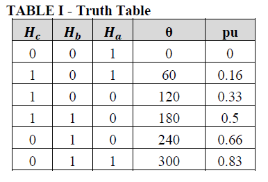
  • Thanks to reply  ChrisClerman . I agree with you. But some applications use Hall Effect sensors for FOC. They use truth table like that. Can ı get better resolution than that truth table using observer/estimator or something like that ?

  • what is the benefit you are hoping to achieve by using this vs. Hall 6-step?

    If you don't need the Hall sensors it is better to just do sensorless FOC.

    If you do require the Hall sensors, why? Start-up performance? Performance under deep iron saturation where observers tend to not work as well?
  • As Chris mentioned, the interpolation logic is need to get enough angle resolution for FOC control with hall sensor. The most simple interpolation logic is as following.

    theta = theta_old + W*Tsample

    theta: angle (rad)

    theta_old: one cycle behind angle (rad)

    W: angular speed (rad/sec)

    Tsample: sampling time (sec)

    This logic need a speed information and you can also use eCAP module for speed measurement. This algorithm has some disadvantages like a poor angle resolution at low speed and angular seam at each hall transition. Nevertheless, this kind of method has been used in many applications because of simple implementation.

    You can also use more advance method for hall interpolation like observer and PLL. But this kind of method need some parameters tuning and need more CPU resource.

  • Thanks for your help Steve and Chris . I want to ask one more question. I am looking at Digital Motor Control math library to calculate speed using eCAP module. I should use SpeedPR macro to calculate speed value by using time stamp value. SpeedPR macro uses BASE RPMvalue.
    HAVACI_Sensored code use

    speed2.BaseRpm = 120*(BASE_FREQ/POLES)

    I do not understand how it's calculated.
  • RPM is calculated with motor electrical frequency(FREQ) and poles(POLES) as following.

    RPS(revolution per second) =  FREQ / PP    ; PP = pole pair (= POLES/2)

                                                  = 2 * FREQ / POLES      

    RPM = RPS * 60

              = 60 * 2 * FREQ / POLES

              = 120 * FREQ / POLES

    BaseRpm is using the same equation as above RPM calcualtion.

    For reference, you can set BASE_FREQ as rated motor electrical frequency or maximum motor electrical frequency. 

  • Thanks again for your help Steve and Chris. I am new in Motor Control methods. So sometimes my questions may be very easy . I am sorry about that. I want to one more question too. I want to make FOC control with Hall effect sensor. How can I implement FOC control with Hall Effect Sensor.