This thread has been locked.

If you have a related question, please click the "Ask a related question" button in the top right corner. The newly created question will be automatically linked to this question.

XDS100v2 Error -1155

Other Parts Discussed in Thread: TMS320F2808

Hello,

I have been trying to solve following problem. I have installed CCS v6.2.0 under Windows 7 

and I have bought emulator XDS100v2. Now I would like to establish connection between

CCS and TMS320F2808 DSP on my control board. I followed the instructions mentioned

in XDS100v2 Quick Start Guide and I have got following error message:

Error connecting to the target Error -1155 @ 0x0. I have checked drivers installation

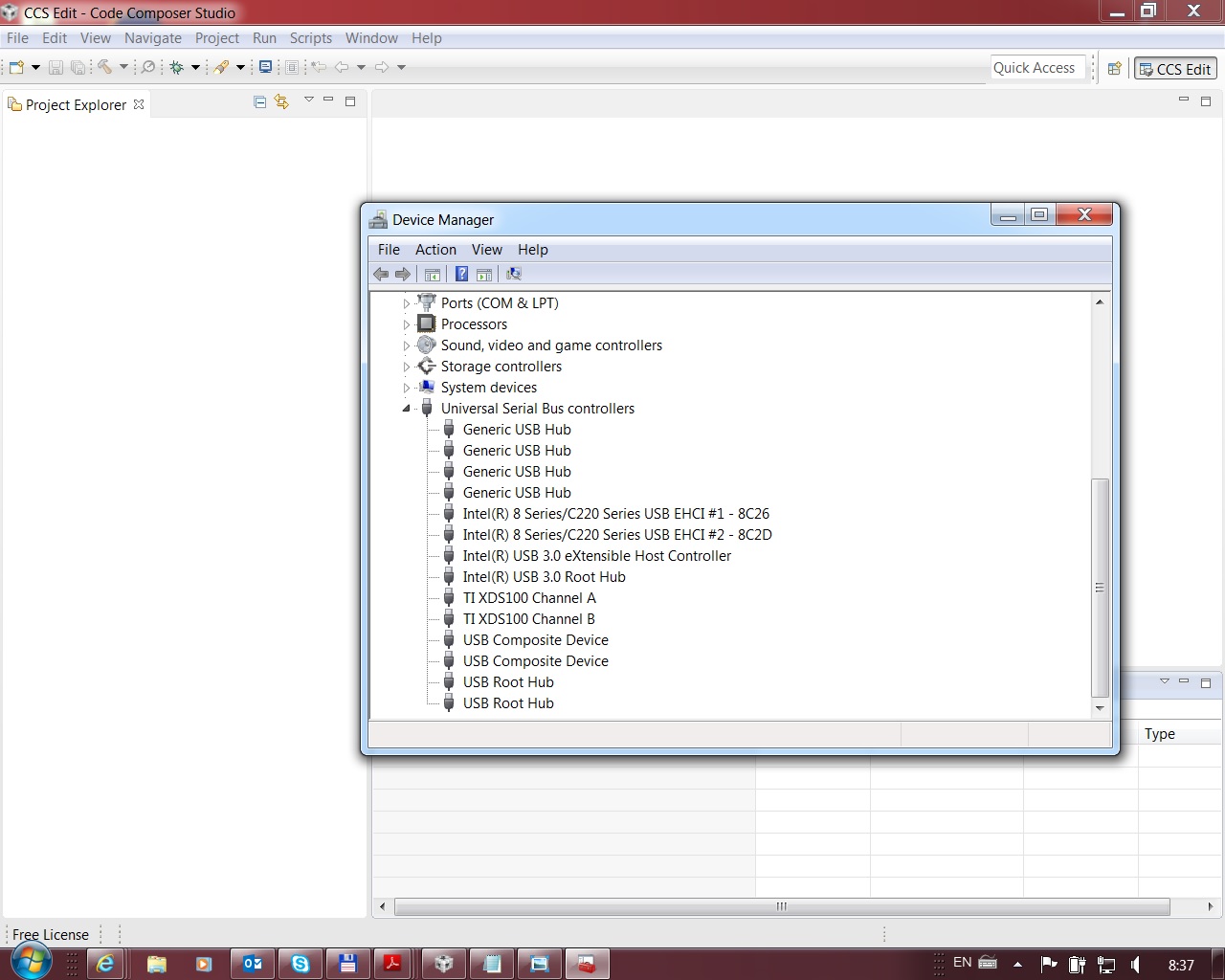
and it looks alright. I have also checked voltage on pin 5 on JTAG header connector. I have found that there is 3.3 V.

The DSP is also alright in my opinion because some state LEDs on the board which are under software control are

blinking. Can somebody give me some advice where to look for the mistake? Thank you in advance.

  • Hi,

    Can you do a 'Test Connection' under Target Configuration window? Paste the results.

    Regards,
    Gautam
  • Hello Gautam,

    thank you for your reaction. Here is the content of my Test Connection window:

    [Start: Texas Instruments XDS100v2 USB Debug Probe_0]

    Execute the command:

    %ccs_base%/common/uscif/dbgjtag -f %boarddatafile% -rv -o -F inform,logfile=yes -S pathlength -S integrity

    [Result]


    -----[Print the board config pathname(s)]------------------------------------

    C:\Users\irhbva\AppData\Local\TEXASI~1\CCS\
    ti\0\0\BrdDat\testBoard.dat

    -----[Print the reset-command software log-file]-----------------------------

    This utility has selected a 100- or 510-class product.
    This utility will load the adapter 'jioserdesusb.dll'.
    The library build date was 'Jul 27 2016'.
    The library build time was '18:31:37'.
    The library package version is '6.0.407.3'.
    The library component version is '35.35.0.0'.
    The controller does not use a programmable FPGA.
    The controller has a version number of '4' (0x00000004).
    The controller has an insertion length of '0' (0x00000000).
    This utility will attempt to reset the controller.
    This utility has successfully reset the controller.

    -----[Print the reset-command hardware log-file]-----------------------------

    The scan-path will be reset by toggling the JTAG TRST signal.
    The controller is the FTDI FT2232 with USB interface.
    The link from controller to target is direct (without cable).
    The software is configured for FTDI FT2232 features.
    The controller cannot monitor the value on the EMU[0] pin.
    The controller cannot monitor the value on the EMU[1] pin.
    The controller cannot control the timing on output pins.
    The controller cannot control the timing on input pins.
    The scan-path link-delay has been set to exactly '0' (0x0000).

    -----[The log-file for the JTAG TCLK output generated from the PLL]----------

    There is no hardware for programming the JTAG TCLK frequency.

    -----[Measure the source and frequency of the final JTAG TCLKR input]--------

    There is no hardware for measuring the JTAG TCLK frequency.

    -----[Perform the standard path-length test on the JTAG IR and DR]-----------

    This path-length test uses blocks of 64 32-bit words.

    The test for the JTAG IR instruction path-length succeeded.
    The JTAG IR instruction path-length is 152 bits.

    The test for the JTAG DR bypass path-length succeeded.
    The JTAG DR bypass path-length is 4 bits.

    -----[Perform the Integrity scan-test on the JTAG IR]------------------------

    This test will use blocks of 64 32-bit words.
    This test will be applied just once.

    Do a test using 0xFFFFFFFF.
    Scan tests: 1, skipped: 0, failed: 0
    Do a test using 0x00000000.
    Scan tests: 2, skipped: 0, failed: 0
    Do a test using 0xFE03E0E2.
    Scan tests: 3, skipped: 0, failed: 0
    Do a test using 0x01FC1F1D.
    Scan tests: 4, skipped: 0, failed: 0
    Do a test using 0x5533CCAA.
    Scan tests: 5, skipped: 0, failed: 0
    Do a test using 0xAACC3355.
    Scan tests: 6, skipped: 0, failed: 0
    All of the values were scanned correctly.

    The JTAG IR Integrity scan-test has succeeded.

    -----[Perform the Integrity scan-test on the JTAG DR]------------------------

    This test will use blocks of 64 32-bit words.
    This test will be applied just once.

    Do a test using 0xFFFFFFFF.
    Scan tests: 1, skipped: 0, failed: 0
    Do a test using 0x00000000.
    Scan tests: 2, skipped: 0, failed: 0
    Do a test using 0xFE03E0E2.
    Scan tests: 3, skipped: 0, failed: 0
    Do a test using 0x01FC1F1D.
    Scan tests: 4, skipped: 0, failed: 0
    Do a test using 0x5533CCAA.
    Scan tests: 5, skipped: 0, failed: 0
    Do a test using 0xAACC3355.
    Scan tests: 6, skipped: 0, failed: 0
    All of the values were scanned correctly.

    The JTAG DR Integrity scan-test has succeeded.

    [End: Texas Instruments XDS100v2 USB Debug Probe_0]
  • Great, your XDS looks fine! Something on your controlCard seems to be triggering the 1155 issue.
    Check your JTAG pins status. Also, check this wiki article:
    processors.wiki.ti.com/.../Debugging_JTAG_Connectivity_Problems

    Regards,
    Gautam
  • Thank you Gautam for your advice. Please can you tell me what  state should I expect on JTAG pins? I have found that voltage on
    all pins (pins of header connector on my control board) except nTRST and GND is 3.3 V. Is it right? Thanks.

  • Yes, that is correct !!