This thread has been locked.

If you have a related question, please click the "Ask a related question" button in the top right corner. The newly created question will be automatically linked to this question.

High Speed ACIM - Unstable operation at higher speed

Other Parts Discussed in Thread: DRV8301, MOTORWARE

Hi

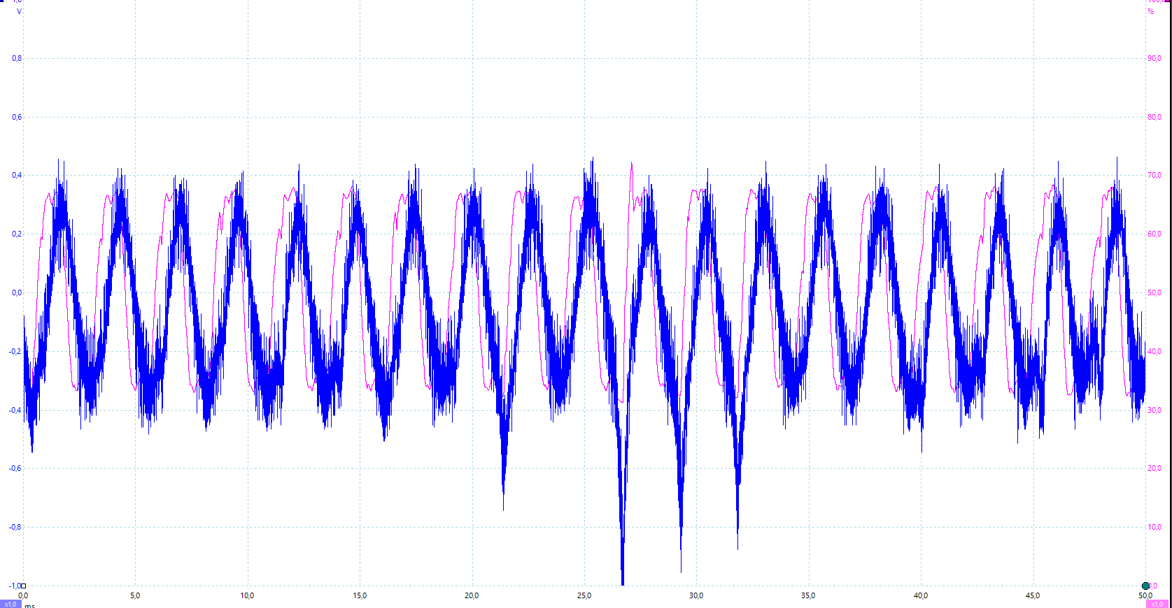
I developed a hardware based on kit DRV8301 RevD using am TMS32028062F (90MHz) prozessor. I have some problems running a motor between 70k RPM and 100k RPM: The current wave form (measured with a current clamp) begins to jump which cause ends in overcurrent after some time. I have two motors from different manufacturer. I have no problem with the weaker one. Maybe because I'm able to operate with a lower Id current.

I'm not sure if the motor parameters are correct because most time lab2b failed to detect Ls_d and Ls_q. Any tips to run a proper ACIM motor identification? Furthermore I'm not sure if the voltage measurement is correct at higher speed because the filter is designed for a lower frequency (USER_VOLTAGE_FILTER_POLE_Hz = 335.648). How do I validate the voltage measurement? Or are the PI-Controller bad optimized?

I set USER_IQ_FULL_SCALE_VOLTAGE_V to bus voltage (48V DC). Is the purpose of this value to limit the voltage if wanted?

About the flux calculation: user.c (USER_MOTOR_RATED_FLUX < (USER_IQ_FULL_SCALE_VOLTAGE_V / (float_t)USER_EST_FREQ_Hz / 0.05)) limits the calculated flux to a value of 0.4 (= 48 / 24kHz / 0.05). My calculation: 0.816 * 48V / 1666Hz = 0.023. Is this calculation correct? I'm running mainISR @ 24kHz so I set ratedFlux to 0.4. Does this setting have any negative side effects? 

I recognized that FAST estimates a lower Speed than measured: @ 51k RPM mueasured FAST estimates 50k RPM; @ 103k RPM measured FAST estimates 100k RPM. Is this variation in tolerance or is it a hint that any setting or motor-Id has a wrong value?

Motor: 

- Type: ACIM; One Pole Pair

- Max Speed: 100k RPM (1666Hz)

- Rated Flux: 0.023 (I have to use  a value of 0.04 caused through the "low" ISR frequency)

- Rated Current: 3.5A

- Max Current: Weak motor 11A; Strong motor: 16A

- Ls_d/Ls_q: Weak motor: ~20uH; Strong motor: ~100uH

- Bus Voltage: 48V DC

Hardware: 

- Frequency PWM: 24kHz

- Frequency ISR: 24kHz

- Inverter: DRV8301

- Current measurement optimized for 20A max (8mOhm Shunt)

- Voltage measurement filter copied from DRV8301_RevD kit (USER_VOLTAGE_FILTER_POLE_Hz = 335.648

Software:

- Based on lab11a

- No PowerWarp; No Rs-Online

- Overmodulation: 0.5774 (100% Duty Cycle)

- USER_IQ_FULL_SCALE_VOLTAGE_V = 48V

Regards Andreas

  • causes:
    a) incorrect parameters
    try using proj_lab02c to ID this motor, but we can't ID all ACI motors, especially low inductance high speed ones. post your parameters
    b) poor current samples at higher speeds
    this is caused by the DRV8301 EVM layout, it has some noise issues
    c) too high of magnetizing current being used, related to a)
    d) poorly tuned controllers
    current gains should be ok, unless Rs and Ls aren't ID'd correctly
    speed gains are not calculated. are you tuning them for stability? if you have stable operation at a lower speed try reducing both Kp and Ki by a factor of 4 and then try high speed again

    the filter pole isn't the issue, though for your own HW I would design this to about 450 Hz

    "I set USER_IQ_FULL_SCALE_VOLTAGE_V to bus voltage (48V DC). Is the purpose of this value to limit the voltage if wanted?"
    No, the purpose is to create a per unit value for all the calculations. Think of USER_ADC as the scaling that converts analog to digital. Think of USER_IQ as the scaling that converts digital to per unit digital to have values between -1 and 1

    "About the flux calculation: user.c (USER_MOTOR_RATED_FLUX < (USER_IQ_FULL_SCALE_VOLTAGE_V / (float_t)USER_EST_FREQ_Hz / 0.05)) limits the calculated flux to a value of 0.4 (= 48 / 24kHz / 0.05). My calculation: 0.816 * 48V / 1666Hz = 0.023. Is this calculation correct? I'm running mainISR @ 24kHz so I set ratedFlux to 0.4. Does this setting have any negative side effects? "
    This is just a variable check, it doesn't limit anything. USER_MOTOR_RATED_FLUX should be set to the value calculated for your ACI based on line voltage and frequency. It is used to fine the MAGNETIZING CURRENT and you should be able to see it stabilize during ID. Review SPRUHJ1 section on motor ID for ACI. Don't change this value due to the user.c error check. If anything just comment out this error check code and proceed.

    "I recognized that FAST estimates a lower Speed than measured: @ 51k RPM mueasured FAST estimates 50k RPM; @ 103k RPM measured FAST estimates 100k RPM. Is this variation in tolerance or is it a hint that any setting or motor-Id has a wrong value?"
    This is caused by an error in motor ID values
  • Thanks for the fast response. I think I have to figure out the proper motor Id first. But I wasn't successful with lab2c. After locking the rotor the current wave form looks very ugly and the current was very high which cause to motor to heat up. My motor parameters:
    #define USER_MOTOR_TYPE MOTOR_Type_Induction
    #define USER_MOTOR_NUM_POLE_PAIRS (1)
    #define USER_MOTOR_Rr (NULL)
    #define USER_MOTOR_Rs (NULL)
    #define USER_MOTOR_Ls_d (NULL)
    #define USER_MOTOR_Ls_q (NULL)
    #define USER_MOTOR_RATED_FLUX (0.042)
    #define USER_MOTOR_MAGNETIZING_CURRENT (NULL)
    #define USER_MOTOR_RES_EST_CURRENT (2.0)
    #define USER_MOTOR_IND_EST_CURRENT (NULL)
    #define USER_MOTOR_MAX_CURRENT (10.0)
    #define USER_MOTOR_FLUX_EST_FREQ_Hz (166.0)
    #define USER_MOTOR_MAX_SPEED_KRPM (100.0)

    I got a very detailed data sheet from the motor manufacturer which includes the reactances X1, X2, XM and resistor values R1 and R2 for different speeds (15,40,50,60,100k RPM).
    I have tried to do the calculation for Ls_d and Ls_q as described in SPRUHJ1F Chapter 4.8. Do I have to use the values for 100k RPM and instaspin performs the scaling automatically? It seems the function softwareUpdate1p6 does perform some scaling - but I don't understand this function completely.

    Are the values of Ls_d and Ls_q always equal?
  • Changing the motor parameters and reducing IdRated made the high speed operation much more stable.

    Now I have to face another problem: To test the controller I start and stop the motor automatically every 20 seconds. After some starts (between 50 and 100) the current wave form becomes ugly (less sinus like) including negative peaks. This cause over current sometimes. The next start shows a good wafeform again. Any ideas?

  • There is some issue on OVM region with ACIM motor in Motorware 16 and before version, especially the OVM region that just one shunt feed is measured. This issue will resolved on new MW17. So I think you would prefer to use the next MW17 version for your system.

    For workaround, this issue can be a little mitigated if you reduce current PI gains about half .  

  • I was able to fix the problem: I changed the code to trigger mainISR by a timer. After every stop I disabled the timer. Now I never disable the timer and the problem has gone.

    Changing the calculated PI parameters haven't improved the result. At the moment I'm able to run up to 92k RPM. Maybe the updates of MW17 help me to reach 100k RPM.

  • " I changed the code to trigger mainISR by a timer."

    what was your reasoning for changing the method of the mainISR?