


Hello Sir,
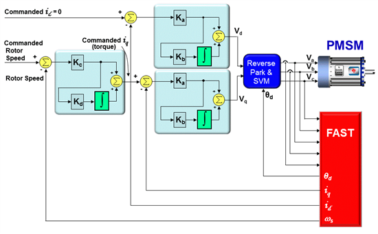
I have bit doubt regarding term bandwidth used with Compensator & software Motor control algorithm code.
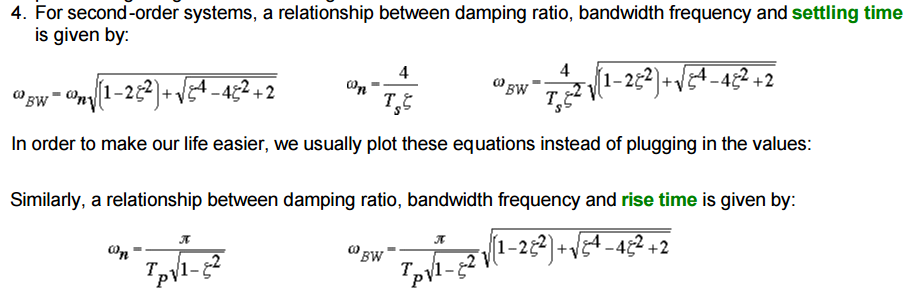
In Frequency response, definition of Bandwidth :--
The bandwidth frequency is defined as the frequency at which the closed-loop magnitude response is equal to -3 dB.
From transient response to unit step function we can derive the Bandwidth of the system using this formula, see the attached picture :--
One thing i know is as per time shift property of Laplase transform, delay in software loop will cause pase lag.
Time delay of T seconds generates a phase shift of -wT radians (w is frequency in rad/sec., T is in sec.).
This link also explain best the math behind phase lag & time delay in LTI systems.
http://lpsa.swarthmore.edu/BackGround/TimeDelay/TimeDelay.html
Following blog from Dave Wilson says :---
https://e2e.ti.com/blogs_/b/motordrivecontrol/archive/2013/04/04/teaching-your-pi-controller-to-behave-part-vi
But in reality, as long as the current controller’s bandwidth is at least 10x higher than the velocity loop unity gain frequency, our tuning procedure is still pretty good at predicting the system response.
What exactly Mr Dave Wilson mean by bandwidth here ?
What is the definition of Bandwidth when using software ?
Suppose i am calling current loop algorithm written in c language every T = 0.1 sec (i.e 10 times faster than velocity loop) then, bandwidth of software current loop = 1/T = 1/0.1 = 10 ?
Suppose i am calling Velocity loop algorithm written in c language every T = 1 sec then, bandwidth of software Velocity loop = 1/T = 1/1 = 1 ?
Have i got it right ?
What is difference or relation between bandwidth of software algorithm code & bandwidth of bode plot ?
Please suggest.
Regards,
Dinesh


