This thread has been locked.

If you have a related question, please click the "Ask a related question" button in the top right corner. The newly created question will be automatically linked to this question.

(Maybe) Clocking Problem with F28337S PTPT, Low-Power-Mode

Other Parts Discussed in Thread: UNIFLASH, CONTROLSUITE, TPS62160

Hello,

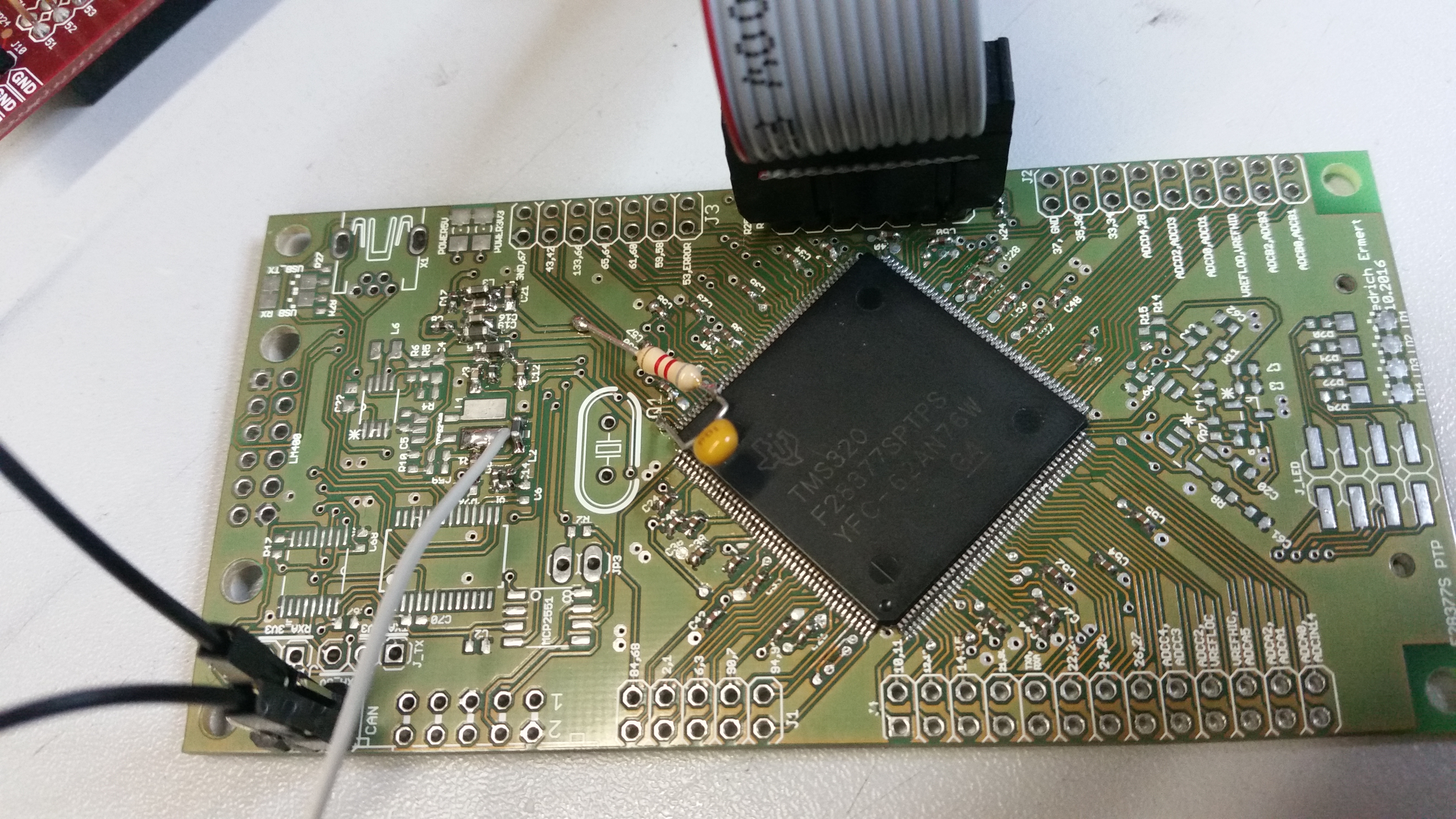
i designed my own PCB with a f28377S PTPT including 256MBit SDRAM on EMIF1.

My problem:

If i try to setup the SysPLL i get always the following errormessage:

Can't Run Target CPU:
(Error -1156 @ 0xB591)
Device may be operating in low-power mode. Do you want to bring it out of this mode? Choose 'Yes' to force the device to wake up and retry the operation. Choose 'No' to retry the operation without waking the device.
(Emulation package 6.0.407.6)

For the tests i am using the examplecode GPIO_TOGGLE from the newest version of ControllSuite.

The problem occours in the function InitSysCtrl();

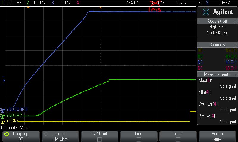
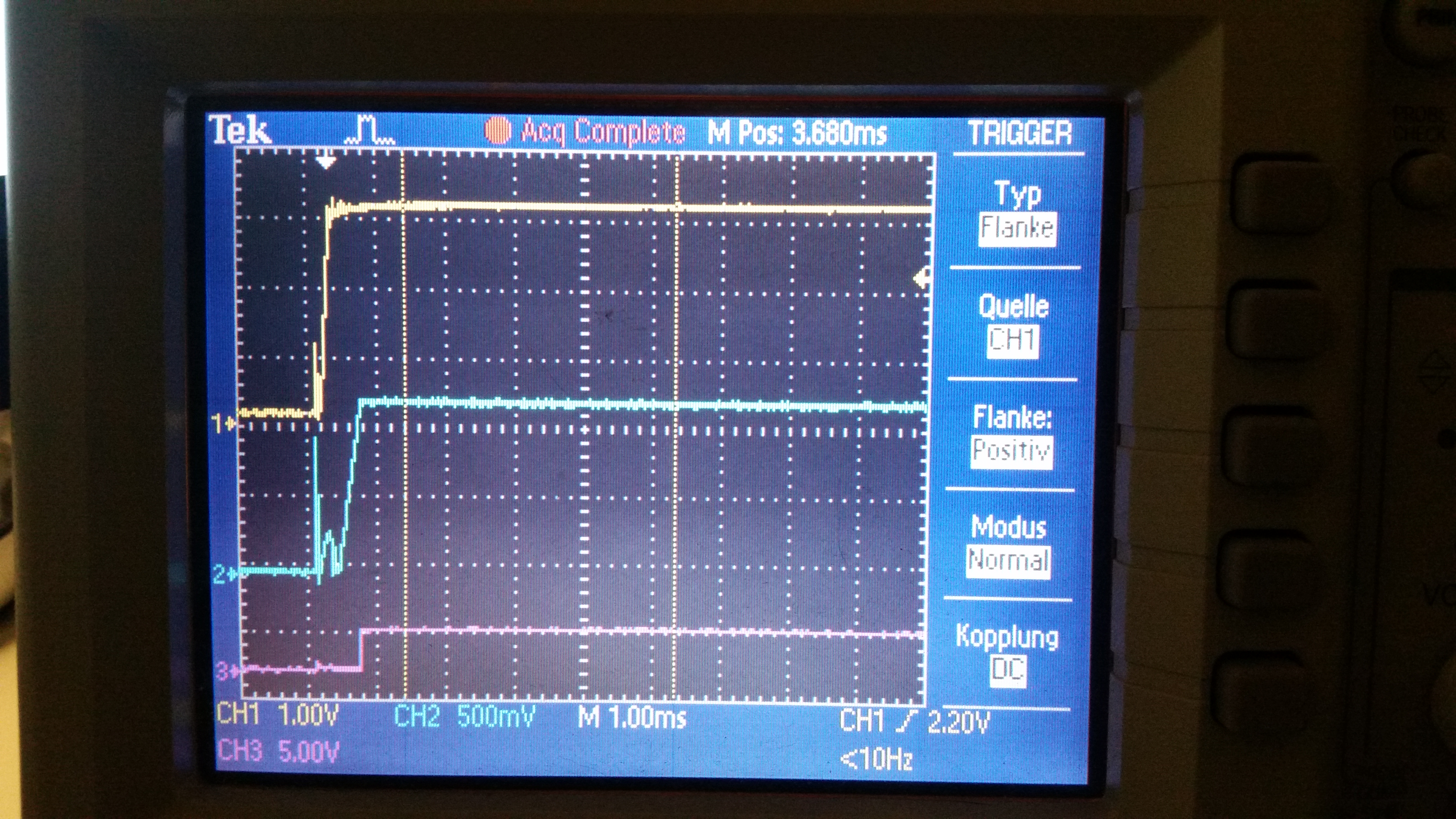
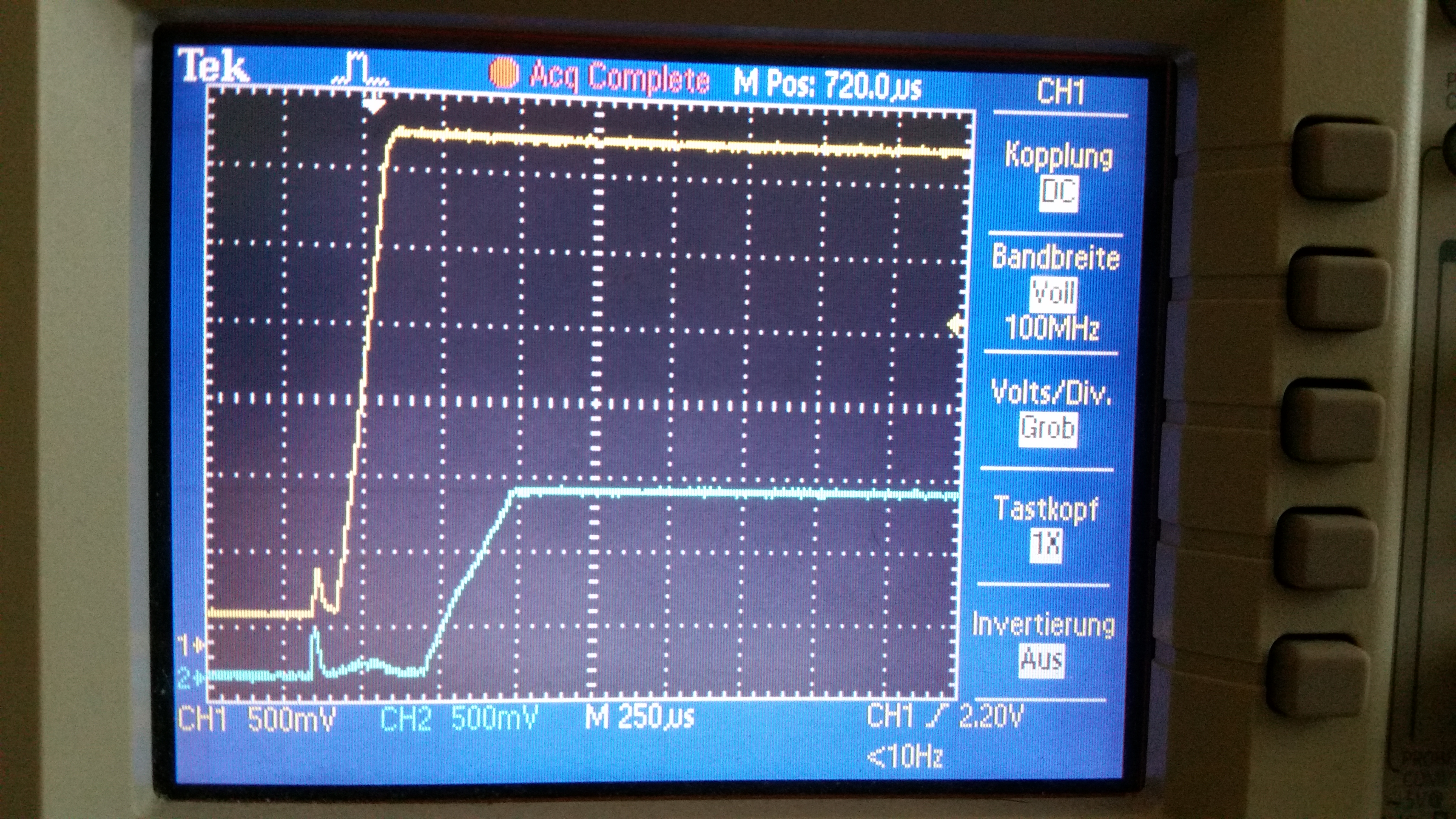
I measured the supply voltages while the problem was happening and they might be ok.

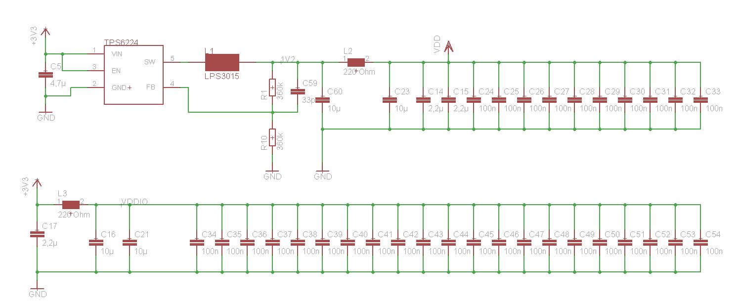
I am using a 10MHz crystal and connected it like on the LAUNCHXL_F28337S.

If i dont use the InitSysCtrl(); the program works fine with internal 10MHz OSC_INT2 and teh GPIOs toggle.

But when i try to configure the SysPll nothing works.

I am using the function:

InitSysPll(XTAL_OSC,IMULT_40,FMULT_0,PLLCLK_BY_2);

I makes no difference whether i use the XTAL_OSC or the INT_OSC2. It doesnt work .

When i try to configure the max frequency of 200MHz (XTAL_OSC) or ~197MHz (INT_OSC2) the error occours when i enable the PLL clk at the line

ClkCfgRegs.SYSPLLCTL1.bit.PLLCLKEN = 1;

When i try to configure a lower frequency like 100MHz the function 

InitSysPll(INT_OSC2,IMULT_19,FMULT_0,PLLCLK_BY_2);

works fine.  But then i get the same problem when i try to init the peripheral clocks at line

InitPeripheralClocks();

When i reduce the number of peripherals to enable, the problem occours in

InitPieVectTable();

What i did until now:

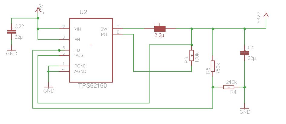
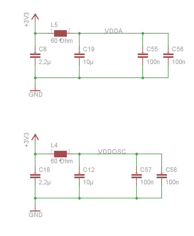
-check the power supply.

- used onboard JTAG of the TMSF28335 evaluation board (its the one i usually work with, but there is no emif supported)

-used Spectrum Digital XDS100 V2 JTAG

-i measured for short-circuits or connection problems on the PCB

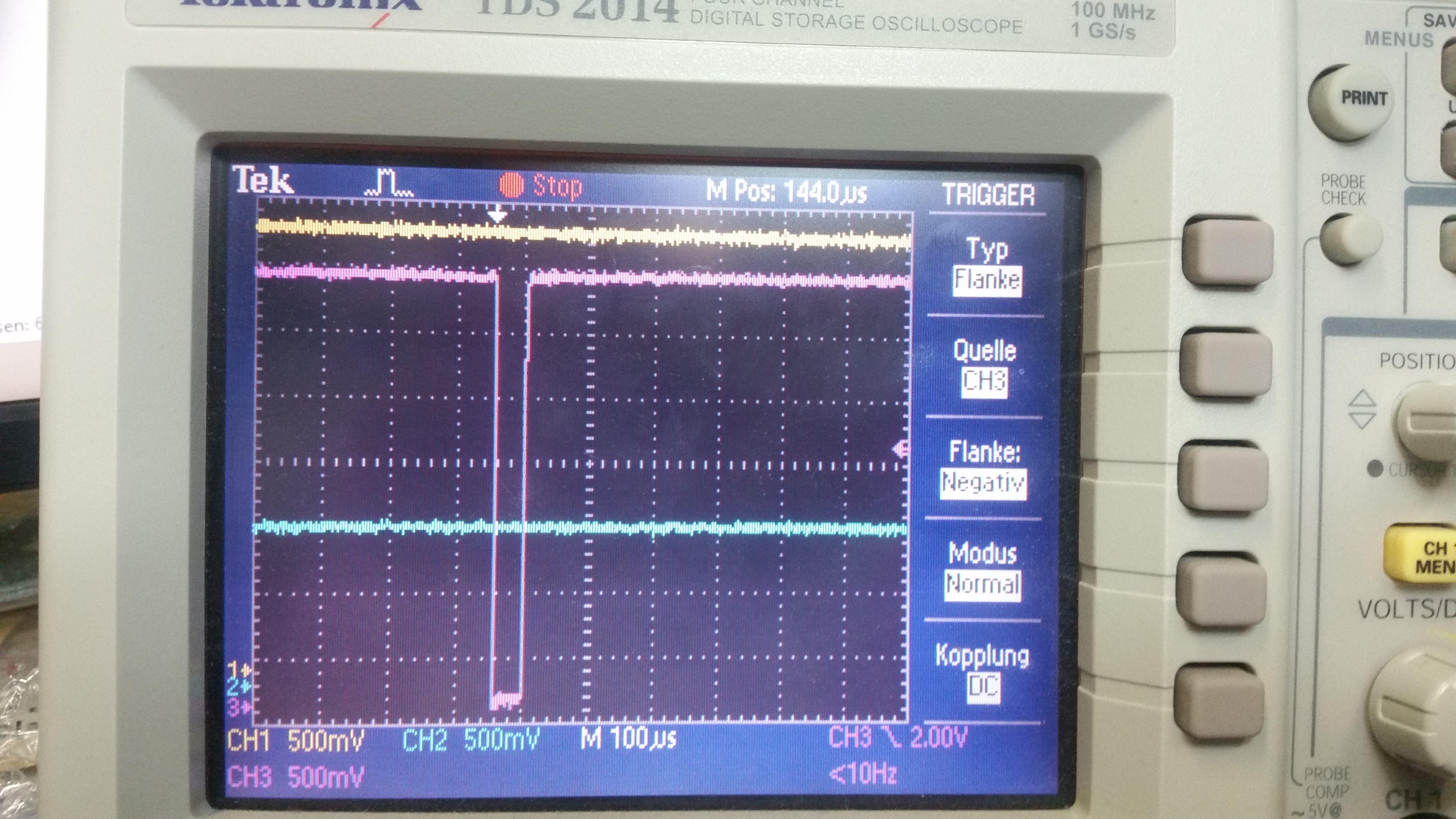
-i tried to have a look at the XCLKOUT  after i configured the pll to a lower frequency with (for example)

GpioCtrlRegs.GPCGMUX1.bit.GPIO73 = 0;
GpioCtrlRegs.GPCMUX1.bit.GPIO73 = 3; // MUS GPIO TO XCLK OUT
GpioCtrlRegs.GPCDIR.bit.GPIO73 = 1;

ClkCfgRegs.CLKSRCCTL3.bit.XCLKOUTSEL = 0; //PUT SYSPLL TO XCLKOUT
ClkCfgRegs.XCLKOUTDIVSEL.bit.XCLKOUTDIV = 2;

But nothing happens on that pin. (?)

-i looked for XRSn Pin, but it's high

- i tried to erase the entire flash with UNIFLASH but it doesnt work. The Result:

[29.10.2016 08:18:50] GEL: C28xx_CPU1: GEL Output: Memory Map Initialization Complete
[29.10.2016 08:18:52] Status: C28xx_CPU1: Erasing Flash memory...
[29.10.2016 08:18:53] Status: C28xx_CPU1: Error: (Error -1135 @ 0xC0CC) The debug probe reported an error. Confirm debug probe configuration and connections, reset the debug probe, and retry the operation. (Emulation package 6.0.407.3)
[29.10.2016 08:18:53] Status: C28xx_CPU1: Trouble Halting Target CPU: (Error -1044 @ 0x0) The debug probe reported an error. Confirm debug probe configuration and connections, reset the debug probe, and retry the operation. (Emulation package 6.0.407.3)
[29.10.2016 08:18:53] Status: C28xx_CPU1: Error: (Error -1135 @ 0xC0CC) The debug probe reported an error. Confirm debug probe configuration and connections, reset the debug probe, and retry the operation. (Emulation package 6.0.407.3)
[29.10.2016 08:18:53] Status: C28xx_CPU1: Unable to determine target status after 20 attempts
[29.10.2016 08:18:53] Status: C28xx_CPU1: Failed to remove the debug state from the target before disconnecting. There may still be breakpoint op-codes embedded in program memory. It is recommended that you reset the emulator before you connect and reload your program before you continue debugging
[29.10.2016 08:19:14] Status: C28xx_CPU1: Error occurred during flash operation: Could not write 0x00000064@Data: target is not connected
[29.10.2016 08:19:14] Status: C28xx_CPU1: Error occurred during flash operation: Could not read 0x00130@Program: target is not connected
[29.10.2016 08:19:14] Status: C28xx_CPU1: Error writing the PLL values. (Flash algorithm returned error code). Operation cancelled.
[29.10.2016 08:19:14] Status: C28xx_CPU1: Flash Programmer: Error initializing device. Please check if the device is locked.
[29.10.2016 08:19:14] Status: C28xx_CPU1: Error occurred during flash operation: Could not write register PC: target is not connected

I have not much experience and i dont know what i can do else.

I hope someone can help me.

Thank u for ur help.

  • I am sorry for the mistake in the title. Its the f28377S of cousre. Not F28337S. I found no option to edit the title.
  • Hi,

    It seems like supply issue to me. Did you monitor the supply while running the program to see if there is any dip on supply voltage when trying the enable the PLL or peripheral clocks?

    Regards,

    Vivek Singh

  • Hi,

    Does the software project work when run on your development kit (I believe its a F28377S LaunchPad)?

    When running the software on your custom board, are you running the software from FLASH or RAM (build config CPU1_FLASH or CPU1_RAM)?

    I know you mentioned that you are using the most recent version of gpio_toggle in controlSUITE, however for clarity what version is this?


    Thank you,
    Brett

  • Hello, thank you very much for your answers at first.


    Yes i already monitored the supplies with a scope, while i enable the PLL and while the error occours. And it looks solid.
    I measured the VVD (1,2V ) and the 3,3V and i cant se any problems.
    Usually i supply the board via USB. I thought maybe 500mA are not enough so i took a 5V, 1A power supply. But no dfference.
    It looks like the supply is not the problem. I also measured all pins of the controller that require a voltage. Its all correct.


    The project works fine at the LAUNCHXL F28377S LaunchPad.
    The version of controlsuite i use is the ControlSUITE 3.4.2.

    I run the project in RAM (CPU1_RAM).
    I tried to switch to CPU1_FLASH in "Properties->General->Configuration-> CPU1_FLASH. But it does not work.
    After i accept the changes and start debug, CCS starts the CPU1_RAM.
    Is there anything else to do for running the Software in FLASH?
  • EDIT:
    Vivek Singh, i agree with you that i might be a supply issue,
    because the INT_OSC2 works if i dont want to configure the PLL. But it doesnt work at any PLL configuration.
    So the crystal might not be the problem, right?
    Is there anything special in the power supply that i have to concider?
    Would it be an advantage, when i load my shematic diagram of the power supply up?
    Is it possible that the internal PLL controller is broken? ( When i soldered the controler i had some problems to solder the heat sink at the bottom of the chip. So i had to heat up the controller for a long time (1-2) minutes. In the end i used heat transfer paste instead soldering the heat sink.)
    Is that a possible reason for the problem?
  • Hi.

    So the crystal might not be the problem, right?

    I would think so since PLL is not working with XTAL_OSC as well.

    Did you try using supply with a bit higher current rating (e.g. 3A) to see if that makes any difference?

    I would let Brett comment on other point you have raised about soldering of part. 

    Regards,

    Vivek Singh

  • Hi,
    no i did not try a supply with higher current rating, because i create the 3,3V by using the TPS62160, that supports just currents up to 1A.
  • Hi Friedrich,

    It would be good to get a scope capture of the power-up waveform in the time scale resolution of 1ms/div with VDDIO, VDD and XRSn from start of VDDIO ramp to ~10ms after. As mentioned by Vivek, it sounds like the device may be current starved when the PLL function is called. Is it possible to capture this and post the waveform here?

    Best Regards,
    Adam Dunhoft
  • Hi Friedrich,

    So the example runs correctly when the PLL is used && the RAM build configuration is used && on your custom board?  Am I understanding you correctly?

    And then if you change to the FLASH build configuration, the PLL appears to be have problem if it is used, correct?

    Sorry, I'm just trying to make sure I understand the problem completely.


    Thank you,
    Brett

  • Hello,


    here i captured a frame of 10ms. Yellow is VDDIO, Blue is VDD and violet is XRSn after powerup, without program code in flash.
    I hope i understood you right.

    [URL=http://www.bilder-upload.eu/show.php?file=035e36-1477944858.jpg][IMG]www.bilder-upload.eu/.../URL]

    (I hope the link works)


    no i gonna explain it:
    The example GPIO_TOGGLE works correctly at the LAUNCHXL F28377S launch pad.
    This example also works on my own PCB if i dont use the PLL, so when i comment the line
    InitSysPll(INT_OSC2,IMULT_20,FMULT_0,PLLCLK_BY_2);
    ( So OSCCLK = INT_OSC2 = 10MHz right? )
    In this case the code works fine.

    At the moment when i use InitSysPll(..); it doesnt work anymore.
    And the behavior is very strange.
    It makes no difference wheter i try to use INT_OSC2 or XTAL_OSC. Both configuration thow the error told above.
    But:
    If i try to configure the max ferquncy (200MHz) the Error occours when i set
    ClkCfgRegs.SYSPLLCTL1.bit.PLLCLKEN = 1;

    If i try to configure a lower frequency like 100Mhz with Int_OSC2, the function InitSysPll(..); works, but then the error occurs later.
    For example when i enable the periherals.
    It feels a little randomly.

    Till now i only used RAM build configuration, cause i cant choose the FLASh build in CCS. If i choose CPU1_FLASH, CCS starts debugging with CPU1_RAM configuration anyway.

    I hope its a little more clear now.

    Thank you for your help.

    Regards
    Friedrich
  • Sorry, it looks like the link doesnt work.
    Here is the direct link:
    www.bilder-upload.eu/show.php
  • Hi Friedrich,

    I am unable to access the host site.  Please attach the image to this thread if possible.

    What I am looking for is with program code in flash and below, but with 1ms/div:

  • Ok here is th capture again ( without code in flash )

    I tried to load the code in flash now. But i cant load the code.

    When i start debugging the following errors occur:

    C28xx_CPU1: GEL Output:
    Memory Map Initialization Complete
    C28xx_CPU1: Error: (Error -1044 @ 0x0) The debug probe reported an error. Confirm debug probe configuration and connections, reset the debug probe, and retry the operation. (Emulation package 6.0.407.6)
    C28xx_CPU1: Unable to determine target status after 20 attempts
    C28xx_CPU1: Failed to remove the debug state from the target before disconnecting. There may still be breakpoint op-codes embedded in program memory. It is recommended that you reset the emulator before you connect and reload your program before you continue debugging
    C28xx_CPU1: Error occurred during flash operation: Could not write 0x00000064@Data: target is not connected
    C28xx_CPU1: Error occurred during flash operation: Could not read 0x00130@Program: target is not connected
    C28xx_CPU1: Error writing the PLL values. (Flash algorithm returned error code). Operation cancelled.
    C28xx_CPU1: File Loader: Memory write failed: Unknown error
    C28xx_CPU1: GEL: File: C:\ti\controlSUITE\device_support\F2837xS\v200\F2837xS_examples_Cpu1\gpio_toggle\cpu01\ccs\CPU1_FLASH\gpio_toggle_cpu01.out: Load failed.
    C28xx_CPU1: Error occurred during flash operation: Could not read register PC: target is not connected
    C28xx_CPU1: Error occurred during flash operation: Could not write 0x0005F800@Data: target is not connected
    C28xx_CPU1: Error occurred during flash operation: Could not write 0x0005FC00@Data: target is not connected
    C28xx_CPU1: Error occurred during flash operation: Could not write 0x00000@Program: target is not connected
    C28xx_CPU1: Error occurred during flash operation: Cannot enable while the target is disconnected
    C28xx_CPU1: Error occurred during flash operation: Could not read 0x00000064@Data: target is not connected
    C28xx_CPU1: Error occurred during flash operation: Could not write 0x00000064@Data: target is not connected
    C28xx_CPU1: Error occurred during flash operation: Failed to run target while trying to execute pwrite_en.alg
    C28xx_CPU1: Flash operation timed out waiting for the algorithm to complete. Operation cancelled.
    C28xx_CPU1: Error occurred during flash operation: Could not write 0x00000064@Data: target is not connected
    C28xx_CPU1: Error occurred during flash operation: Could not read 0x0005D20E@Data: target is not connected
    C28xx_CPU1: Error occurred during flash operation: Could not write 0x0005D20E@Data: target is not connected
    C28xx_CPU1: Error occurred during flash operation: Could not read 0x0005D20E@Data: target is not connected
    C28xx_CPU1: Error occurred during flash operation: Could not write 0x0005D20E@Data: target is not connected
    C28xx_CPU1: Error occurred during flash operation: Could not read 0x0005D22E@Data: target is not connected
    C28xx_CPU1: Error occurred during flash operation: Could not read 0x0005D208@Data: target is not connected
    C28xx_CPU1: Error occurred during flash operation: Could not write 0x0005D208@Data: target is not connected
    C28xx_CPU1: Error occurred during flash operation: Could not read 0x0005D208@Data: target is not connected
    C28xx_CPU1: Error occurred during flash operation: Could not write 0x0005D208@Data: target is not connected
    C28xx_CPU1: Error occurred during flash operation: Could not read 0x0005D222@Data: target is not connected
    C28xx_CPU1: Error occurred during flash operation: Could not write 0x0005D222@Data: target is not connected
    C28xx_CPU1: Error occurred during flash operation: Could not write 0x0005D214@Data: target is not connected
    C28xx_CPU1: Error occurred during flash operation: Could not read 0x0005D20E@Data: target is not connected
    C28xx_CPU1: Error occurred during flash operation: Could not write 0x0005D20E@Data: target is not connected
    C28xx_CPU1: Error occurred during flash operation: Could not write 0x0005D20E@Data: target is not connected
    C28xx_CPU1: Error occurred during flash operation: Could not write 0x0005D222@Data: target is not connected
    C28xx_CPU1: Error occurred during flash operation: Could not write 0x00000@Program: target is not connected
    C28xx_CPU1: Error occurred during flash operation: Cannot enable while the target is disconnected
    C28xx_CPU1: Error occurred during flash operation: Could not read 0x00000064@Data: target is not connected
    C28xx_CPU1: Error occurred during flash operation: Could not write 0x00000064@Data: target is not connected
    C28xx_CPU1: Error occurred during flash operation: Failed to run target while trying to execute pwrite_dis.alg
    C28xx_CPU1: Flash operation timed out waiting for the algorithm to complete. Operation cancelled.
    C28xx_CPU1: Error occurred during flash operation: Could not write 0x00000064@Data: target is not connected
    C28xx_CPU1: Error occurred during flash operation: Could not write register PC: target is not connected

    What did i wrong? :-O

  • Due to the voltage peaks at the beginning of powering up i captured a new picture with higher voltage and time resolution:

  • Friedrich,

    Are you no longer able to load code to flash? I would like to see the waveforms when your pattern is loaded to flash.

    Also, is this a TMS or TMX device? Please check device markings.

    Best Regards,
    Adam Dunhoft
  • I am still not able to write the code into the flash.

    The errors again with another example of controllSUITE:

    C28xx_CPU1: Error: (Error -1044 @ 0x0) The debug probe reported an error. Confirm debug probe configuration and connections, reset the debug probe, and retry the operation. (Emulation package 6.0.407.6)

    C28xx_CPU1: Unable to determine target status after 20 attempts

    C28xx_CPU1: Failed to remove the debug state from the target before disconnecting.  There may still be breakpoint op-codes embedded in program memory.  It is recommended that you reset the emulator before you connect and reload your program before you continue debugging

    C28xx_CPU1: Error occurred during flash operation: Could not write 0x00000064@Data: target is not connected

    C28xx_CPU1: Error occurred during flash operation: Could not read 0x00130@Program: target is not connected

    C28xx_CPU1: Error writing the PLL values. (Flash algorithm returned error code). Operation cancelled.

    C28xx_CPU1: File Loader: Memory write failed: Unknown error

    C28xx_CPU1: GEL: File: C:\ti\controlSUITE\device_support\F2837xS\v200\F2837xS_examples_Cpu1\sci_echoback\cpu01\ccs\CPU1_FLASH\sci_echoback_cpu01.out: Load failed.

    C28xx_CPU1: Error occurred during flash operation: Could not read register PC: target is not connected

    C28xx_CPU1: Error occurred during flash operation: Could not write 0x0005F800@Data: target is not connected

    C28xx_CPU1: Error occurred during flash operation: Could not write 0x0005FC00@Data: target is not connected

    C28xx_CPU1: Error occurred during flash operation: Could not write 0x00000@Program: target is not connected

    C28xx_CPU1: Error occurred during flash operation: Cannot enable while the target is disconnected

    C28xx_CPU1: Error occurred during flash operation: Could not read 0x00000064@Data: target is not connected

    C28xx_CPU1: Error occurred during flash operation: Could not write 0x00000064@Data: target is not connected

    C28xx_CPU1: Error occurred during flash operation: Failed to run target while trying to execute pwrite_en.alg

    C28xx_CPU1: Flash operation timed out waiting for the algorithm to complete. Operation cancelled.

    C28xx_CPU1: Error occurred during flash operation: Could not write 0x00000064@Data: target is not connected

    C28xx_CPU1: Error occurred during flash operation: Could not read 0x0005D20E@Data: target is not connected

    C28xx_CPU1: Error occurred during flash operation: Could not write 0x0005D20E@Data: target is not connected

    C28xx_CPU1: Error occurred during flash operation: Could not read 0x0005D20E@Data: target is not connected

    C28xx_CPU1: Error occurred during flash operation: Could not write 0x0005D20E@Data: target is not connected

    C28xx_CPU1: Error occurred during flash operation: Could not read 0x0005D22E@Data: target is not connected

    C28xx_CPU1: Error occurred during flash operation: Could not read 0x0005D208@Data: target is not connected

    C28xx_CPU1: Error occurred during flash operation: Could not write 0x0005D208@Data: target is not connected

    C28xx_CPU1: Error occurred during flash operation: Could not read 0x0005D208@Data: target is not connected

    C28xx_CPU1: Error occurred during flash operation: Could not write 0x0005D208@Data: target is not connected

    C28xx_CPU1: Error occurred during flash operation: Could not read 0x0005D222@Data: target is not connected

    C28xx_CPU1: Error occurred during flash operation: Could not write 0x0005D222@Data: target is not connected

    C28xx_CPU1: Error occurred during flash operation: Could not write 0x0005D214@Data: target is not connected

    C28xx_CPU1: Error occurred during flash operation: Could not read 0x0005D20E@Data: target is not connected

    C28xx_CPU1: Error occurred during flash operation: Could not write 0x0005D20E@Data: target is not connected

    C28xx_CPU1: Error occurred during flash operation: Could not write 0x0005D20E@Data: target is not connected

    C28xx_CPU1: Error occurred during flash operation: Could not write 0x0005D222@Data: target is not connected

    C28xx_CPU1: Error occurred during flash operation: Could not write 0x00000@Program: target is not connected

    C28xx_CPU1: Error occurred during flash operation: Cannot enable while the target is disconnected

    C28xx_CPU1: Error occurred during flash operation: Could not read 0x00000064@Data: target is not connected

    C28xx_CPU1: Error occurred during flash operation: Could not write 0x00000064@Data: target is not connected

    C28xx_CPU1: Error occurred during flash operation: Failed to run target while trying to execute pwrite_dis.alg

    C28xx_CPU1: Flash operation timed out waiting for the algorithm to complete. Operation cancelled.

    C28xx_CPU1: Error occurred during flash operation: Could not write 0x00000064@Data: target is not connected

    C28xx_CPU1: Error occurred during flash operation: Could not write register PC: target is not connected

    I used the unlock function of UNIFLASH, but the error still occurs.

    I still cant erase the FLASH with UNIFLASH:

    [1.11.2016 18:10:43] GEL: C28xx_CPU1: GEL Output: Memory Map Initialization Complete
    [1.11.2016 18:10:44] Status: C28xx_CPU1: Erasing Flash memory...
    [1.11.2016 18:10:47] Status: C28xx_CPU1: Error: (Error -1044 @ 0x0) The debug probe reported an error. Confirm debug probe configuration and connections, reset the debug probe, and retry the operation. (Emulation package 6.0.407.3)
    [1.11.2016 18:10:47] Status: C28xx_CPU1: Unable to determine target status after 20 attempts
    [1.11.2016 18:10:47] Status: C28xx_CPU1: Failed to remove the debug state from the target before disconnecting. There may still be breakpoint op-codes embedded in program memory. It is recommended that you reset the emulator before you connect and reload your program before you continue debugging
    [1.11.2016 18:11:07] Status: C28xx_CPU1: Error occurred during flash operation: Could not write 0x00000064@Data: target is not connected
    [1.11.2016 18:11:07] Status: C28xx_CPU1: Error occurred during flash operation: Could not read 0x00130@Program: target is not connected
    [1.11.2016 18:11:07] Status: C28xx_CPU1: Error writing the PLL values. (Flash algorithm returned error code). Operation cancelled.
    [1.11.2016 18:11:07] Status: C28xx_CPU1: Flash Programmer: Error initializing device. Please check if the device is locked.
    [1.11.2016 18:11:07] Status: C28xx_CPU1: Error occurred during flash operation: Could not write register PC: target is not connected.
    UNIFLASH might have the same problem as CCS.
    Is it a hardware problem?
    I cant find anything in the internet about that problem.
    I talso tried to boot in WAIT BOOT (GPIO72 High, and GPIO84 LOW) before i erase the flash.
    I dont know if this was nessesary. It was the only hint i fount about that problem.
    And it did not work.

    I have never seen this problem.

    Is there sombody who knows a possible cause for this error?

    Is it possible that this problem sticks together with my problem to configure the PLL?

  • Is your device a TMX or TMS device. Please check the markings on the device.

    Best Regards,
    Adam Dunhoft
  • Oh sorry. I forgot it in my last post.

    Its a TMS device.
  • Friedrich,

    OK. Let's take a step back for a minute. Now that you are having trouble erasing and loading your program to Flash, can you still run your code from RAM or is that not working now either?

    Best Regards,
    Adam Dunhoft
  • Hi Adam,
    yes. I am still able to run my code from RAM, as long as i dont use the InitSysPll(...); function (like discribed) .
  • Hi Ermert,

    Just to make sure device did not get damage during soldering process, could you replace the device on this board and check if new device works fine?

    Regards,

    Vivek Singh

  • Hi Vivek,
    yes i will do it tomorrow at first.

    Thank u all for your help with that. :-)

    Regards
    Friedrich Ermert
  • Hi,
    i soldered a new controller onto my board.
    Writing to FLASH gives the same reaction like before:

    C28xx_CPU1: GEL Output:
    Memory Map Initialization Complete
    C28xx_CPU1: Error: (Error -1044 @ 0x0) The debug probe reported an error. Confirm debug probe configuration and connections, reset the debug probe, and retry the operation. (Emulation package 6.0.222.0)
    C28xx_CPU1: Unable to determine target status after 20 attempts
    C28xx_CPU1: Failed to remove the debug state from the target before disconnecting. There may still be breakpoint op-codes embedded in program memory. It is recommended that you reset the emulator before you connect and reload your program before you continue debugging
    C28xx_CPU1: Error occurred during flash operation: Could not write 0x00000064@Data: target is not connected
    C28xx_CPU1: Error occurred during flash operation: Could not read 0x00130@Program: target is not connected
    C28xx_CPU1: Error writing the PLL values. (Flash algorithm returned error code). Operation cancelled.
    C28xx_CPU1: File Loader: Memory write failed: Unknown error
    C28xx_CPU1: GEL: File: C:\Users\FErmert\Documents\workspace\gpio_toggle_cpu01\CPU1_FLASH\gpio_toggle_cpu01.out: Load failed.
    C28xx_CPU1: Error occurred during flash operation: Could not read register PC: target is not connected
    C28xx_CPU1: Error occurred during flash operation: Could not write 0x0005F800@Data: target is not connected
    C28xx_CPU1: Error occurred during flash operation: Could not write 0x0005FC00@Data: target is not connected
    C28xx_CPU1: Error occurred during flash operation: Could not write 0x00000@Program: target is not connected
    C28xx_CPU1: Error occurred during flash operation: Cannot enable while the target is disconnected
    C28xx_CPU1: Error occurred during flash operation: Could not read 0x00000064@Data: target is not connected
    C28xx_CPU1: Error occurred during flash operation: Could not write 0x00000064@Data: target is not connected
    C28xx_CPU1: Error occurred during flash operation: Failed to run target while trying to execute pwrite_en.alg
    C28xx_CPU1: Flash operation timed out waiting for the algorithm to complete. Operation cancelled.
    C28xx_CPU1: Error occurred during flash operation: Could not write 0x00000064@Data: target is not connected
    C28xx_CPU1: Error occurred during flash operation: Could not read 0x0005D20E@Data: target is not connected
    C28xx_CPU1: Error occurred during flash operation: Could not write 0x0005D20E@Data: target is not connected
    C28xx_CPU1: Error occurred during flash operation: Could not read 0x0005D20E@Data: target is not connected
    C28xx_CPU1: Error occurred during flash operation: Could not write 0x0005D20E@Data: target is not connected
    C28xx_CPU1: Error occurred during flash operation: Could not read 0x0005D22E@Data: target is not connected
    C28xx_CPU1: Error occurred during flash operation: Could not read 0x0005D208@Data: target is not connected
    C28xx_CPU1: Error occurred during flash operation: Could not write 0x0005D208@Data: target is not connected
    C28xx_CPU1: Error occurred during flash operation: Could not read 0x0005D208@Data: target is not connected
    C28xx_CPU1: Error occurred during flash operation: Could not write 0x0005D208@Data: target is not connected
    C28xx_CPU1: Error occurred during flash operation: Could not read 0x0005D222@Data: target is not connected
    C28xx_CPU1: Error occurred during flash operation: Could not write 0x0005D222@Data: target is not connected
    C28xx_CPU1: Error occurred during flash operation: Could not write 0x0005D214@Data: target is not connected
    C28xx_CPU1: Error occurred during flash operation: Could not read 0x0005D20E@Data: target is not connected
    C28xx_CPU1: Error occurred during flash operation: Could not write 0x0005D20E@Data: target is not connected
    C28xx_CPU1: Error occurred during flash operation: Could not write 0x0005D20E@Data: target is not connected
    C28xx_CPU1: Error occurred during flash operation: Could not write 0x0005D222@Data: target is not connected
    C28xx_CPU1: Error occurred during flash operation: Could not write 0x00000@Program: target is not connected
    C28xx_CPU1: Error occurred during flash operation: Cannot enable while the target is disconnected
    C28xx_CPU1: Error occurred during flash operation: Could not read 0x00000064@Data: target is not connected
    C28xx_CPU1: Error occurred during flash operation: Could not write 0x00000064@Data: target is not connected
    C28xx_CPU1: Error occurred during flash operation: Failed to run target while trying to execute pwrite_dis.alg
    C28xx_CPU1: Flash operation timed out waiting for the algorithm to complete. Operation cancelled.
    C28xx_CPU1: Error occurred during flash operation: Could not write 0x00000064@Data: target is not connected
    C28xx_CPU1: Error occurred during flash operation: Could not write register PC: target is not connected

    But when i write to RAM there are some differences.

    I am able to use the XTAL_OSC or the INT_OSC2 to sett the PLL now.
    BUT:
    It just works when the SysClk i want to configure is lower than 50 MHz.

    InitSysPll(XTAL_OSC,20,0,2); (10MHz * 200 /4) WORKED NOW.

    If i try to set a higher frequency i get the same problems like before,

    So I played a little with the TCLK frequency in the target configuration.
    I set it to 10.0MHz.

    After this i was able to set the PLL to 75 MHz!

    InitSysPll(XTAL_OSC,30,0,2);

    But no matter what i do:
    i cant execute the line
    GpioCtrlRegs.GPBDIR.all = 0x00001FFF; // All outputs
    of the function
    void Gpio_select(void)
    of the project GPIO_TOGGLE.

    independend to the frequency i get the issue:

    C28xx_CPU1: Can't Single Step Target Program: (Error -1156 @ 0x1CB) Device may be operating in low-power mode. Do you want to bring it out of this mode? Choose 'Yes' to force the device to wake up and retry the operation. Choose 'No' to retry the operation without waking the device. (Emulation package 6.0.222.0)

    ( There is no short circuit between the GPIOS )

    When i comment this line, the project GPIO_TOGGLE runs at 75MHz by crystal.

    I hope this brings a little light in the dark for someone.

    I am getting to a point where i dont have any ideas anymore.
  • Hello,
    i soldered a new controller onto my board.
    Writing to flash throws the same error message like before.

    But there are some little differeces when i write to RAM.

    I am able to use XTAL_OSC or INT_OSC2 to configure the PLL.
    But it works only to frequencies up to 50 MHZ
    InitSysPll(XTAL_OSC,20,0,2); (10MHz * 20 / 4) WORKS!
    After this i played a little bit with TCLK in the target configuration:
    I set it to 10MHz.

    Now i am able to set the PLL to 75MHz:
    InitSysPll(XTAL_OSC,30,0,2);
    But for this i have to disable the most of Peripheral clocks, else i get the error
    Device may be operating in low-power mode

    And there is another problem.
    I am still using GPIO_TOGGLE
    and i must comment the line
    GpioCtrlRegs.GPBDIR.all = 0x00001FFF; // All outputs
    inf the function
    void Gpio_select(void)
    independent on the SysClk this line always throws the "low-power mode" error.

    There no short circuit between the GPIOs or GND

    I am getting to a point where i dont have any ideas anymore.
    Ihope someone has any ideas.
  • Hello,
    i soldered a new controler onto my board.
    When i try to write my code into flash i get the same issue like before.

    When i write into RAM there are some little differences.

    I am able to use XTAL_OSC or INT_OSC2 to configure my SysPll.
    But it cant get higher then 50 MHz
    InitSysPll(XTAL_OSC,20,0,2); WORKS!
    Fort hat i have to disable most oft he peripheral clocks.
    At higher frequencies or with all perpheral clocks enabled i get the same error like before (low power mdoe).

    After this i played a little bit with TCLK in the target configuration.
    I set it to 10.0 MHz
    Now i can configure the PLL to 75 MHz
    InitSysPll(XTAL_OSC,30,0,2); WORKS!

    And now there is another problem.

    I am still using GPIO_TOGGLE.
    I have to comment the line
    GpioCtrlRegs.GPBDIR.all = 0x00001FFF;
    In the function
    void Gpio_select(void)
    otherwise i get the „low power mode“ error at this line, independent on the SysClk.

    There is no short circuit between the GPIOs or to GND.

    I am getting to a point where i have no ideas anymore.
  • Friedrich,

    Please try this while running from RAM:

    1. Set the PLL to 200MHz
    2. Comment out InitPeripheralClocks()
    3. Single step through InitSysPLL()
    4. Does device crash?

    Best Regards,
    Adam Dunhoft
  • Hi Adam,

    yes. At the last line

    ClkCfgRegs.SYSCLKDIVSEL.bit.PLLSYSCLKDIV = divsel; // (divsel = 1)

    of the function it crashes.
    i called:
    InitSysPll(XTAL_OSC,40,0,1);

    Regards,
    Friedrich Ermert
  • Sorry that "Spam" posts, i was logged in with another account from work. and my browser crashed everytime i did a post.
  • Hello Adam,

    again i dont know whether my last post got out, so i write it again.

    Yes the controller crashes at the last line of teh function:
    ClkCfgRegs.SYSCLKDIVSEL.bit.PLLSYSCLKDIV = divsel;
    Regards,
    Friedrich
  • Hi Friedrich,

    OK. Great. To determine if this is a supply or board issue:

    1. Setup the scope to monitor VDDIO, VDD and XRSn
    2. Set the time resolution to 200us
    3. Set the trigger to VDDIO high to low at 2.97V.
    4. Run your pattern
    5. Report the results and send with waveform

    Also, can you please send your schematic or at least the power management section?

    Best Regards,
    Adam Dunhoft
  • Hi Adam,

    im not sure if unhderstood u right.

    I should watch the falling edge of VDDIO when i started my software on the controller? This is what i did now.

    There is no fallig edge. The voltage drops not under this 2,97V when the error occurs or to any other time. So i have no capture.

    The capture of teh startup did i already post. Should i capture a new one?

    Here is my Powermanagement.

    I can also upload my whole EAGLE Design or more single parts if u want.

    Tanke you and best regards,

    Friedrich

  • Hi Friedrich,

    OK. That is good. Change the trigger of the scope to XRSn high to low transition at 2V and run pattern again. When XRSn goes low, we want to view both rails to see if either rail voltage droops too low.

    Best Regards,
    Adam Dunhoft
  • Hi Friedrich,

    After looking at your schematic, I am now more convinced of a current sourcing issue. The TPS6224x has a max current output of 300mA. The above experiment should help us determine that is an issue.

    Best Regards,
    Adam Dunhoft
  • Friedrich,

    Do you have ability to supply the VDD rail from a bench power supply?

    Best Regards,
    Adam Dunhoft
  • Hello Adam,

    yes i have. I will do it tomorrow in the morning.

    Thank you and have a good evening.
    Regars,
    Friedrich Ermert
  • Friedrich,

    If you look at the Power Consumption Summary section in the datasheet, you will see that the typical current consumption seen on the VDD rail for the general currents testing done at bench is 245mA with a max seen at 360mA (these are only typical numbers).

    I believe the issue you are running into is that the supply used for VDD is not providing enough current. My recommendation is to choose a supply IC which can handle the current load and leave plenty of margin for current spikes.

    Best Regards,
    Adam Dunhoft
  • Hello Adam,
    i supplied the VDD by a bank power supply now. No difference.
    After that i supplied the 3,3V also extern. Also no difference.
  • Hi Adam,
    i am getting crazy with this problem.
    So i soldered an completly new PCB, without an own powersupply and any peripherals.
    I only soldered a controler and its capacitors to the board. I supllied the board by an external powersupply with exactly 1.2V and 3.3V. I also soldered the parts to make VDDIO, VDDOSC and VDDA outof the 3,3V.

    The problem is still the same.

    Best regards
    Friedrich Ermert
  • Hi Friedrich,

    1. What was the current limit set to on both external power supplies?
    2. Can you set the VDDIO voltage to 3.63V and the VDD voltage to 1.26V and try to run your pattern?

    Best Regards,
    Adam Dunhoft
  • Hi Adam,
    the current limits are:
    1A at 3,3V source
    and 5A at 1,2V source.
    And the supply shows that these limits are not reached.

    Now i configured 3,63V and 1,26V.
    No difference.
  • This is what it looks like at the moment.

    The controler ist new. 

    Only the supply voltages are connected to the controller.

    And i am still not able to configure that PLL.....

    (The resistor and capacity go to XRSn pin. There is no short circuit. ) =) 

  • Friedrich,

    With this setup (external supplies) can you run your application without setting the PLL?

    Best Regards,
    Adam Dunhoft
  • Yes its the same situation like before.
    Without InitSysPll(), everything works fine. And if i configure the pll with frequencies lower than 50MHz (XTAL_OSC or INT_OSC2), it works too.(but in this case i have to disable most of the peripheral clocks, else the controler crashes at enablePeripheralClocks() )

    And programming to flash did not work until now.

    Regards
    Friedrich
  • Friedrich,

    On your PCB, do you have a VDD power plane with vias from the VDD pins down to that plane? How wide are your power and GND traces?

    Best Regards,
    Adam Dunhoft
  • Hi Adam,
    no. My PCB has only two layers. My VDD and VDDIO tracees are 0,4064 mm wide.(to blocking capacities)
    And they are 0,254mm wide from the capacities to the pins of the controler.
    VDD and VDDIO traces lie on the BOT layer, and they go with vias to the blocking capacities on TOP layer.

    For GND i have filled all empty spaces on TOP and BOT layer (with orphans) and in most cases i used two vias to connect GND.

    Do u think that could be a problem?
    0,4064 mm should be enough to drive up to 1,5A i think.
  • Hi Friedrich,

    Yes. For external layers in air, I believe that 0.4064 mm trace width should be sufficient. This is puzzling. Whenever I have seen this type of behavior on bench where the device goes into reset when setting PLL or initializing the peripheral clocks, it has been due to a voltage droop on the VDD supply. Being unable to erase/load to flash also points to a current supply issue.

    1. Do you have the ability to capture VDD current with your scope?
    2. Is the controller which you soldered to the new board a different device from the original, or the same device?

    Best Regards,
    Adam Dunhoft
  • Hi Adam,

    yes the device is exaclty the same like on the other PCB.

    On monday i am goining to borrow a current probe from the laboratory for switched supplies. 

    I will post a capture of VDD current then. 

    I hope we'll find the problem. 

    Tankyou very much for your help till now Adam. :-)

    Best regards and have a nice weekend,

    Friedrich Ermert