This thread has been locked.

If you have a related question, please click the "Ask a related question" button in the top right corner. The newly created question will be automatically linked to this question.

TMDXIDDK379D: different current values for LEM sensor and Sigma Delta measurement

Other Parts Discussed in Thread: TMDXIDDK379D, AMC1304M25

Hello !


I use the TMDXIDDK379D Motor control demoboard with the original SW-project. I want to compare the current measurementd of the LEMs and Sigma-Deltas. I use a current source in Phase W - so a current of 5.0A flows through the LEM current sensor and the Sigma-Delta-Shunt. In the debug window, I can look at the values (current_sensor[1 or 2].Bs):


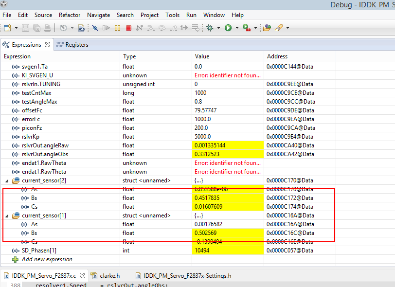
The base value for the emitter shunt measurement ist 9.98A, so I must multiply the normalized values (from -1 to 1) with 9.98A. So the LEM sensor measured 5.016A, the Sigma-Delta only 4.509A. Why this big different?

The realization in the software seems to be right for me.


/*******************************************************/

/* Sinc filter Module */

/*******************************************************/

       //Configure Data filter modules filter type, OSR value and enable / disable data filter

       // 16 bit data representation is chosen for OSR 128 using Sinc3, from the table in the TRM

       // the max value represented for OSR 128 using sinc 3 is +/-2097152 i.e. 2^21

       // to represent this in 16 bit format where the first bit is sign shift by 6 bits

       Sdfm_configureData_filter(1, FILTER1, FILTER_ENABLE, SINC3, OSR_128, DATA_16_BIT, SHIFT_6_BITS);

       Sdfm_configureData_filter(1, FILTER2, FILTER_ENABLE, SINC3, OSR_128, DATA_16_BIT, SHIFT_6_BITS);

       Sdfm_configureData_filter(1, FILTER3, FILTER_ENABLE, SINC3, OSR_128, DATA_16_BIT, SHIFT_6_BITS);


inline void currentSensorSuite()

{

       volatile int16 temp;  // temp variable used to avoid warning msgs


       current_sensor[SHUNT_CURRENT_SENSE-1].As = (float)IFB_SV_PPB* ADC_PU_PPB_SCALE_FACTOR;

       current_sensor[SHUNT_CURRENT_SENSE-1].Bs = (float)IFB_SW_PPB* ADC_PU_PPB_SCALE_FACTOR;

       current_sensor[SHUNT_CURRENT_SENSE-1].Cs = -current_sensor[SHUNT_CURRENT_SENSE-1].Cs

                                                       -current_sensor[SHUNT_CURRENT_SENSE-1].Bs;


       current_sensor[LEM_CURRENT_SENSE-1].As   = (float)IFB_LEMV_PPB* ADC_PU_PPB_SCALE_FACTOR * LEM_TO_SHUNT;

       current_sensor[LEM_CURRENT_SENSE-1].Bs   = (float)IFB_LEMW_PPB* ADC_PU_PPB_SCALE_FACTOR * LEM_TO_SHUNT;

       current_sensor[LEM_CURRENT_SENSE-1].Cs   = -current_sensor[LEM_CURRENT_SENSE-1].Cs

                                                       -current_sensor[LEM_CURRENT_SENSE-1].Bs;


       current_sensor[SD_CURRENT_SENSE-1].As    = ((temp=SDFM1_READ_FILTER1_DATA_16BIT)*SD_PU_SCALE_FACTOR -

                                                        offset_SDFM1) * SDFM_TO_SHUNT;

       current_sensor[SD_CURRENT_SENSE-1].Bs    = ((temp=SDFM1_READ_FILTER2_DATA_16BIT)*SD_PU_SCALE_FACTOR -

                                                        offset_SDFM2) * SDFM_TO_SHUNT;

       current_sensor[SD_CURRENT_SENSE-1].Cs    = -current_sensor[SD_CURRENT_SENSE-1].Cs

                                                       -current_sensor[SD_CURRENT_SENSE-1].Bs;


       SD_Phasen[0] = SDFM1_READ_FILTER1_DATA_16BIT;

       SD_Phasen[1] = SDFM1_READ_FILTER2_DATA_16BIT;


       return;

}


Thanks for your help !


  • Martin,

    It is hard for us to provide any meaningful suggestion without knowing about your hardware setup. But, these were some of the questions which came to my mind assuming your hardware setup is solid with respect to SD-modulator and LEM sensor.

    1) Are you making sure to use high precision SD-modulator? There are different types of SD-modulators available in market. Hope you had done proper analysis to choose the right one for your application.

    2) SDFM works asynchronous to SYSCLK as it works on SD-Cx. How are you making sure you reading your currents at the right moment?
    Are you clocking your modulator using PWM? Are you using SDSYNC option (FILRESn) option in SDFM?

    3) Have you played around with increasing DOSR?

    Regards,
    Manoj
  • Different sensors have different hardware gains, and hence were scaled to  represent the value of what the emitter side shunt measurement ckt will show.

    #define LEM_TO_SHUNT 1.206637 // (12.0/9.945)

    #define SDFM_TO_SHUNT 1.41131 // (12.5/0.8906)/9.945


    But your observation puzzles me, can you verify if the shunt resistor used in SDFM ckt is 20mOhms.

  • Hi Manoj,

    Hi Ramesh,


    thanks very much for your fast answers.


    I haven't change something in hardware and software. It's "your" TI-board TMDXIDDK379D and the sample project software which I got from control suite. The SD-modulators are "your" AMC1304M25. I used the software settings in the sample project.

    It's an 20mOhm shunt. The voltage drop over the shunt is 100mV with 5.0A --> OK.

    I also tried to measure the SD-Bit-stream on the data line. On my scope, I can made an average over the bit-stream - that matches the functionallity of SD-modulators very well. I get the calculated values, except for only a few mV difference. So I'm sure, the electrical part is OK.

    I haven't made any changes in the point of time, concerning current measurement. On the other hand, it's an static DC current and the values themselves are very stabil.  

    I havent't played with DOSR yet.


    The defines for current conversion of the different sensors are activ in the code:


    // ************************************************************************

    // Scaling factors to bring all current feedbacks to normal scale

    //   matching with shunt based measurement

    // With shunt, 1.0pu current == 9.945A

    //       LEM,   1.0pu current == 12A

    //       SDFM, 0.8906pu current == 12.5A

    // ************************************************************************

    #define LEM_TO_SHUNT   1.206637   // (12.0/9.945)

    #define SDFM_TO_SHUNT   1.41131   // (12.5/0.8906)/9.945


    I hope my description ist understandable for you.


    Regards,

    Martin

  • ok, when I get to retest, I will post my reply. Thanks for the msg.

    rgds,

    ramesh

  • Hi Manoj,

    Hi Ramesh,


    I modified the board to make my error clear and elimate other influences like calculation factors. I remove the SD-shunt and put an input voltage on ist pads. So I can regulate the input voltage of the AMC1304 directly. In software, I create a new integer variable which shows the filter results directly, without any normalization or offset correction:


    SD_Phase = SDFM1_READ_FILTER2_DATA_16BIT;

    SD_Phase is an integer, so ist range is -32768 to 32768. In my test, I use only a positiv voltage, so 0… 32768.

    I get the following results:


    0mV                                 --> 10

    100mV (equal to 5.0A) --> 10480

    200mV (equal to 10A) --> 20940

    250mV (equal to 12.5A) --> 26200

    320mV (nonlinear range of modulator) --> 32256


    It' s a little bit confusing, because the 26200 (for 250mV) are 80% of the whole of range. In the controller datasheet I found several sentences, which describe an SD-modulator output as 80% duty cycle in the case of max input voltage. I only see that as an generell information about modulators and not as an important fact for the demodulator.


    Regards,

    Martin