

Hi ;
I am completly new in Embeddede Programming, and I need to use TMS320F28027PT that will convert it's ch0 (ADC conversion) and also I am using DAC MCP4921 (12
bit ) that is used throgh SPI interface to convert back to analog ,the ADC conversion we get from cho .
In the begining I need to simulate that in Proteus.for that I use your CCstudioV6( the latest one) and the controlsuite for c2000 family.
I wrote the C code with the help of your examples, but I get the Following errors ,
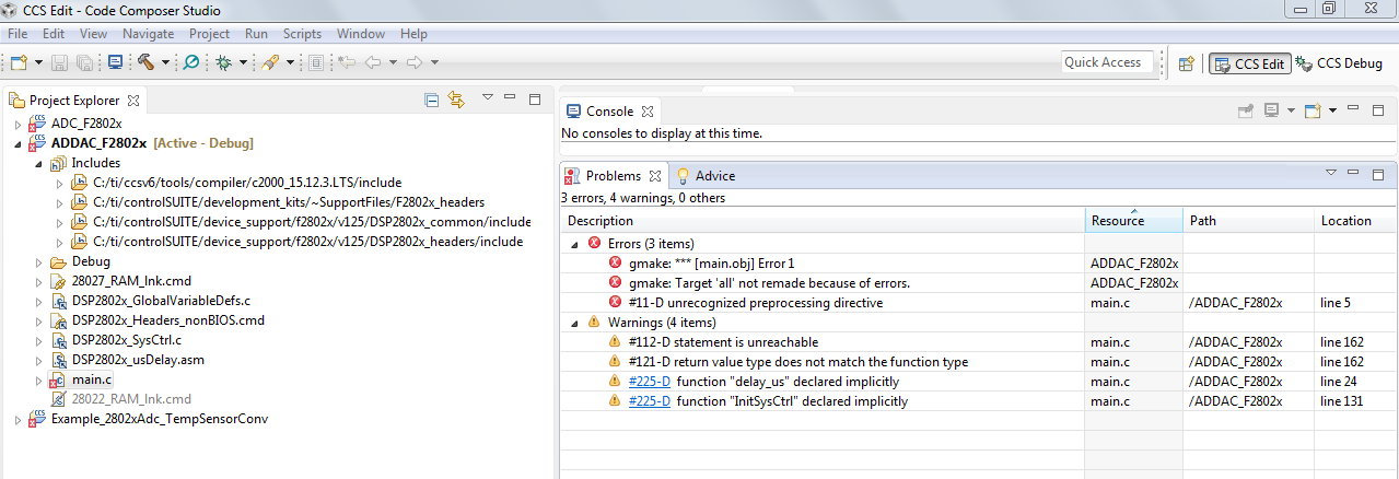
I do submit the Complete program: and the Console window shot, and the errors.
Thanks for your Cooperations
Ahmad.
/* This Program Should Take Sample from ch0 and convert it and using SPI we should send converted data to a 12 bit DAC
MCP4921 */
#include "DSP2802x_Device.h"
#use delay(clock=20000000)
void InitAdc(void)
{
asm(" EALLOW"); // Enable EALLOW protected register access
//--- Reset the ADC module
AdcRegs.ADCCTL1.bit.RESET = 1; // Reset the ADC
// Must wait 2 ADCCLK periods for the reset to take effect.
// Note that ADCCLK = SYSCLKOUT for F2802x/F2803x devices.
asm(" NOP");
asm(" NOP");
//--- Power-up and configure the ADC
AdcRegs.ADCCTL1.all = 0x00E4; // Power-up reference and main ADC
delay_us(5); // Wait 5us after power-up before using the ADC
//--- SOC0 configuration
AdcRegs.ADCSAMPLEMODE.bit.SIMULEN0 = 0; // SOC0 in single sample mode (vs. simultaneous mode)
AdcRegs.ADCSOC0CTL.bit.TRIGSEL = 7; // Trigger using ePWM2-ADCSOCA
AdcRegs.ADCSOC0CTL.bit.CHSEL = 0; // Convert channel ADCINA0 (ch0)
AdcRegs.ADCSOC0CTL.bit.ACQPS = 6; // Acquisition window set to (6+1)=7 cycles
AdcRegs.ADCINTSOCSEL1.bit.SOC0 = 0; // No ADCINT triggers SOC0. TRIGSEL field determines trigger.
AdcRegs.SOCPRICTL.bit.SOCPRIORITY = 0; // All SOCs handled in round-robin mode
//--- ADCINT1 configuration
AdcRegs.INTSEL1N2.bit.INT1CONT = 1; // ADCINT1 pulses regardless of ADCINT1 flag state
AdcRegs.INTSEL1N2.bit.INT1E = 1; // Enable ADCINT1
AdcRegs.INTSEL1N2.bit.INT1SEL = 0; // EOC0 triggers ADCINT1
PieCtrlRegs.PIEIER1.bit.INTx1 = 1; // Enable ADCINT1 in PIE group 1
IER |= 0x0001; // Enable INT1 in IER to enable PIE group
//--- Finish up
AdcRegs.ADCCTL1.bit.ADCENABLE = 1; // Enable the ADC
asm(" EDIS"); // Disable EALLOW protected register access
} // end InitAdc()
void spi_init()
{
SpiaRegs.SPICCR.all =0x000F; // Reset on, rising edge, 16-bit char bits
SpiaRegs.SPICTL.all =0x0006; // Enable master mode, normal phase,
// enable talk, and SPI int disabled.
SpiaRegs.SPIBRR =0x007F;
SpiaRegs.SPICCR.all =0x009F; // Relinquish SPI from Reset
SpiaRegs.SPIPRI.bit.FREE = 1; // Set so breakpoints don't disturb xmission
}
void spi_xmit(Uint16 a)
{
SpiaRegs.SPITXBUF=a;
}
void spi_fifo_init()
{
// Initialize SPI FIFO registers
SpiaRegs.SPIFFTX.all=0xE040;
SpiaRegs.SPIFFRX.all=0x2044;
SpiaRegs.SPIFFCT.all=0x0;
}
void InitGpio(void)
{
EALLOW;
GpioCtrlRegs.GPAPUD.bit.GPIO0 = 1; // Disable pull-up on GPIO0 (EPWM1A)
GpioCtrlRegs.GPAPUD.bit.GPIO16 = 1; // Disable pull-up on GPIO0 (EPWM1A)
//GpioCtrlRegs.GPAPUD.bit.GPIO17 = 1; // Disable pull-up on GPIO0 (EPWM1A)
GpioCtrlRegs.GPAPUD.bit.GPIO18 = 1; // Disable pull-up on GPIO0 (EPWM1A)
GpioDataRegs.GPASET.bit.GPIO0 = 1; // condition for GPIO0 to be an output
GpioDataRegs.GPACLEAR.bit.GPIO0 = 1;
GpioDataRegs.GPASET.bit.GPIO16 = 1;
GpioDataRegs.GPACLEAR.bit.GPIO16 = 1;
//GpioDataRegs.GPASET.bit.GPIO17 = 1;
//GpioDataRegs.GPACLEAR.bit.GPIO17 = 1;
GpioDataRegs.GPASET.bit.GPIO18 = 1;
GpioDataRegs.GPACLEAR.bit.GPIO18 = 1;
GpioCtrlRegs.GPADIR.bit. GPIO0 = 1;// GPIO0 is output
GpioCtrlRegs.GPADIR.bit.GPIO16 = 1;
//GpioCtrlRegs.GPADIR.bit.GPIO17 = 1;
GpioCtrlRegs.GPADIR.bit.GPIO18 = 1;
EDIS;
}
int DAC(int16 value )
{
EALLOW;
int rdata, mask;
InitGpio();
GpioDataRegs.GPADAT.bit.GPIO0 = 1; //ChipSelect = 1; for Enable DAC
spi_init();
spi_fifo_init();
spi_xmit(value);// write to DAC
while(SpiaRegs.SPIFFRX.bit.RXFFST !=1) { }
rdata = SpiaRegs.SPIRXBUF;
mask = rdata & 0x0FFF;
GpioDataRegs.GPADAT.bit.GPIO0 = 0; //ChipSelect = 0; // needs to Disable DAC
return(mask);
}
void main(void) {
int16 temp, shift;
InitSysCtrl(); // Step 1. Initialize System Control:
// Step 2. Initialize GPIO:
// Enable XCLOCKOUT to allow monitoring of oscillator 1
EALLOW;
GpioCtrlRegs.GPAMUX2.bit.GPIO18 = 3; //enable XCLOCKOUT through GPIO mux
SysCtrlRegs.XCLK.bit.XCLKOUTDIV = 2; //XCLOCKOUT = SYSCLK
for(;;)
{
InitAdc();
//Force start of conversion on SOC0 and SOC1
AdcRegs.ADCSOCFRC1.all = 0x03;
//Wait for end of conversion.
while(AdcRegs.ADCINTFLG.bit.ADCINT1 == 0){} //Wait for ADCINT1
AdcRegs.ADCINTFLGCLR.bit.ADCINT1 = 1; //Clear ADCINT1
temp = AdcResult.ADCRESULT0;
shift = temp << 4;
shift = temp*4096/3.3 ;
DAC(shift);
}
return 0;
}
***************************************************************************************
The cOnsole Window:
*** Build of configuration Debug for project ADDAC_F2802x ****
"C:\\ti\\ccsv6\\utils\\bin\\gmake" -k all
'Building file: ../main.c'
'Invoking: C2000 Compiler'
"C:/ti/ccsv6/tools/compiler/c2000_15.12.3.LTS/bin/cl2000" -v28 -ml -mt --include_path="C:/ti/controlSUITE/device_support/f2802x/v125/DSP2802x_common/include"
--include_path="C:/ti/controlSUITE/development_kits/~SupportFiles/F2802x_headers" --include_path="C:/ti/ccsv6/tools/compiler/c2000_15.12.3.LTS/include" --
include_path="C:/ti/controlSUITE/device_support/f2802x/v125/DSP2802x_headers/include" -g --display_error_number --diag_warning=225 --diag_wrap=off --
preproc_with_compile --preproc_dependency="main.d" "../main.c"
>> Compilation failure
subdir_rules.mk:28: recipe for target 'main.obj' failed
"../main.c", line 5: error #11-D: unrecognized preprocessing directive
"../main.c", line 24: warning #225-D: function "delay_us" declared implicitly
"../main.c", line 131: warning #225-D: function "InitSysCtrl" declared implicitly
"../main.c", line 162: warning #112-D: statement is unreachable
"../main.c", line 162: warning #121-D: return value type does not match the function type
1 error detected in the compilation of "../main.c".
gmake: *** [main.obj] Error 1
gmake: Target 'all' not remade because of errors.
**** Build Finished ****
********************************************************************************************

-
Ask a related question
What is a related question?A related question is a question created from another question. When the related question is created, it will be automatically linked to the original question.

