This thread has been locked.

If you have a related question, please click the "Ask a related question" button in the top right corner. The newly created question will be automatically linked to this question.

ADC software trigger 28377D question

Other Parts Discussed in Thread: CONTROLSUITE

Hi there,

I am using the DSP 28377D, and in my software I have one PWM interrupt (occurring when TBCTR = 0). When the interrupt occurs I need to read a the ADC value. I wanted to do use the software triggered ADC, but I am not sure if I am using it correctly. The relevant sections of my code are below:

ADC (channel A0) settings:

void SetupADC_A(Uint16 channel)
{
	Uint16 acqps;

	//determine minimum acquisition window (in SYSCLKS) based on resolution (SYSCLK = 200MHz)
	if(ADC_RESOLUTION_12BIT == AdcaRegs.ADCCTL2.bit.RESOLUTION){
		acqps = 19; //75ns ((14+1)*(1/200MHz) ) 14 is the default value
	}
	else { //resolution is 16-bit
		acqps = 63; //320ns ((63+1)*(1/200MHz))
	}

	//Select the channels to convert and end of conversion flag
	EALLOW;
	AdcaRegs.ADCSOC0CTL.bit.CHSEL = 0; 
	AdcaRegs.ADCSOC0CTL.bit.ACQPS = acqps; //sample window is 100 SYSCLK cycles
	AdcaRegs.ADCSOC0CTL.bit.TRIGSEL = 0; //forced trigger by software
}

now, when the main software reaches the pwm interrupt:

interrupt void epwm6_isr(void) {

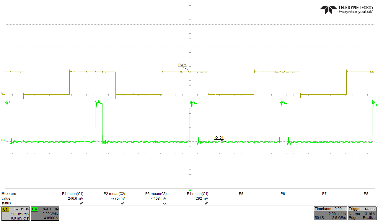
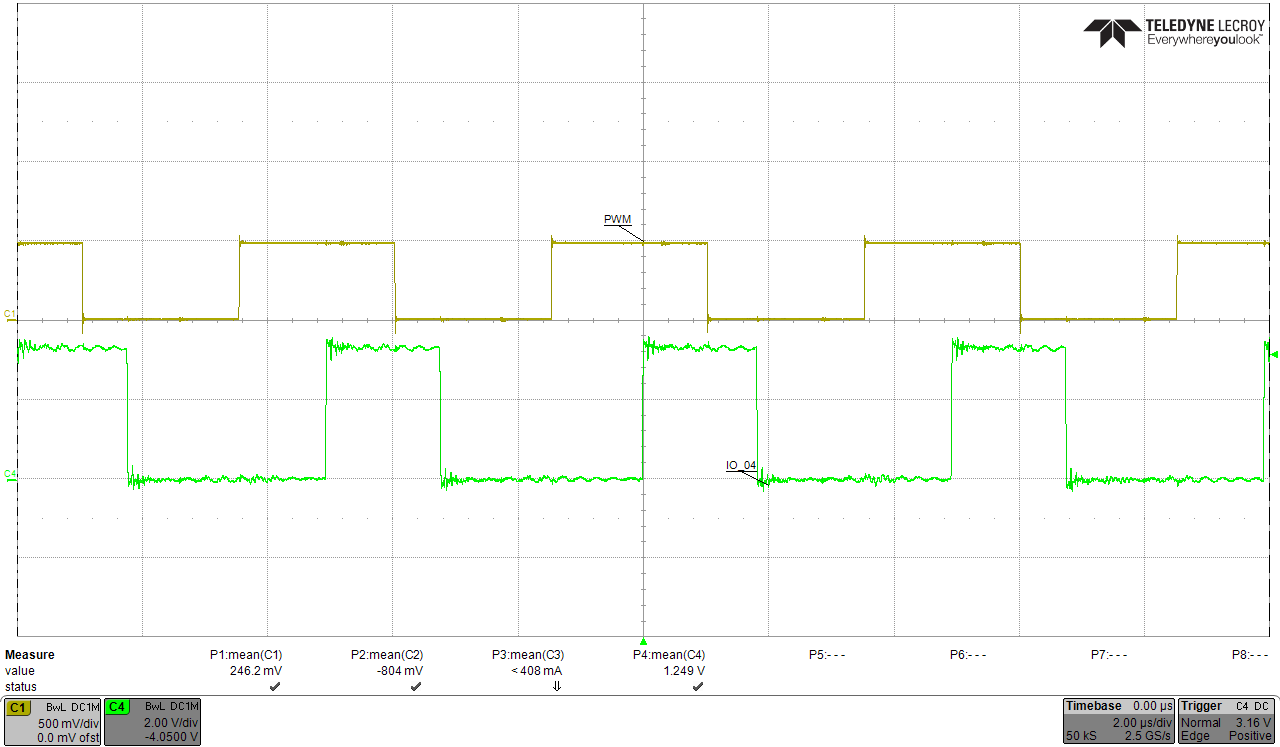
AdcaRegs.ADCSOCFRC1.bit.SOC0 = 1; // Software forced start of conversion in ADC A0 (input current)

i_read = (-0.004346)*((double)(AdcaResultRegs.ADCRESULT0)) + 8.217;
EPwm6Regs.ETCLR.bit.INT = 1; // clear EPWM6 INT flag

PieCtrlRegs.PIEACK.all = PIEACK_GROUP3;

}

In the pwm interrupt I would like to read the ADC content and scale the result to update the value of the current "i_read" as highlighted in the code.

Is there anything else needed to make sure that I get the correct result from the ADC? 

Thank you very much for your answer.

Leo

  • Hi Leo,

    Did you do an ADC check with this configuration ie inputting 3.3V and GND to ADCINA0? Do you get respective digital values on the Expression window?

    Regards,
    Gautam
  • Hi Gautam,

    thank you for your kind answer.

    Feeding the output of the PWM pin (having a duty ratio = 0.5) to the ADC input, I read the value 4095 in the expression window for my AdcaResultRegs.ADCRESULT0 as expected, since I am using trailing edge PWM, and the interrupt where I software-force the ADC at TBCTR = 0 (picture below).

    It seems that the adc is converting the value correctly with the settings as per my previous question. What is your opinion? Do I need further settings to software-start the ADC?

    Thanks a lot,

    Leo

  • Hi Leo,

    I think with the code you have you will get a reading, but it will be the reading from the previous ePWM cycle. This is because it takes some time for the ADC to receive the trigger, sample the signal, and then process the sample into a digital result. The ADC result register is not updated until this process is complete (until then the old results are still in the result register).

    Have a look at the software-triggered ADC example in ControlSUITE. Here, there is this code segment:

    //
    //wait for ADCA to complete, then acknowledge flag
    //
    while(AdcaRegs.ADCINTFLG.bit.ADCINT1 == 0);
    AdcaRegs.ADCINTFLGCLR.bit.ADCINT1 = 1;

    Which is waiting for the ADCINT flag to get set, indicating that the conversion is complete.

    You could add this (along with the proper configurations to ensure that the ADC end-of-conversion sets this flag) to your code, but a better flow would probably be this:

    -ePWM event triggers ADC conversion(s).
    -last ADC conversion triggers ADC ISR
    -in the ADC ISR read the ADC sample, do your control logic, and update "i_read"

    Here you have no need for an ePWM ISR - the ADC ISR takes its place.
  • Hello Devin,

    thanks a lot, your answer is very useful.

    So, the way I read the adc inside the pwm interrupt (as in my top question) is not necessarily correct, as it does not ensure that the ADC has finished the conversion.

    Now, the reality is that my software must execute 4 adc readings inside the interrupt. So I can do it as follows: (case 1)

    interrupt void epwm6_isr(void) {
    
    	//********************************************
    	//	ADC measurements (input, output voltages)
    	//********************************************
    
    	IO_04_ON();
    
    
    	AdcbRegs.ADCSOCFRC1.bit.SOC4 = 1; // Software forced start of conversion in ADC B4 (input voltage)
    	AdcbResult4 = AdcbResultRegs.ADCRESULT4;
    	vpv_r = (-0.03962) * ((double) (AdcbResult4)) + 74.92; // measurement #1
    
    	AdcaRegs.ADCSOCFRC1.bit.SOC2 = 1; // Software forced start of conversion in ADC A2 (input current)
    	AdcaResult2 = AdcaResultRegs.ADCRESULT2;
    	ipv_r = (-0.004346) * ((double) (AdcaResult2)) + 8.217; // measurement #2
    
    	AdcdRegs.ADCSOCFRC1.bit.SOC0 = 1; // Software forced start of conversion in ADC D0 (output voltage)
    	AdcdResult0 = AdcdResultRegs.ADCRESULT0;
    	vo_r = (-0.08432) * ((double) (AdcdResult0)) + 159.5; // measurement #3
    
    
    	AdccRegs.ADCSOCFRC1.bit.SOC2 = 1;// Software forced start of conversion in ADC C2 (output current)
    	AdccResult2 = AdccResultRegs.ADCRESULT2;
    	io_r = (-0.01759)*((double)(AdccResult2)) + 33.16; // measurement #4 
    
            IO_04_OFF(); // and the interrupt continues with control code, and ePWM CMPA/B update

    but, if I understood correctly this is not the best way. A better way would be the following, in which I set the flags to make sure that the ADC has finished the conversion: (case 2)

    interrupt void epwm6_isr(void) {
    
    	//********************************************
    	//	ADC measurements (input, output voltages)
    	//********************************************
    
    	IO_04_ON();
    
    
    	AdcbRegs.ADCSOCFRC1.bit.SOC4 = 1; // Software forced start of conversion in ADC B4 (input voltage)
    	while (AdcbRegs.ADCINTFLG.bit.ADCINT1 == 0)
    		; // wait for ADCB to complete, then acknowledge flag
    	AdcbRegs.ADCINTFLGCLR.bit.ADCINT1 = 1;
    	AdcbResult4 = AdcbResultRegs.ADCRESULT4;
    	vpv_r = (-0.03962) * ((double) (AdcbResult4)) + 74.92; // measurement #1
    
    	AdcaRegs.ADCSOCFRC1.bit.SOC2 = 1; // Software forced start of conversion in ADC A2 (input current)
    	while (AdcaRegs.ADCINTFLG.bit.ADCINT1 == 0)
    		; // wait for ADCA to complete, then acknowledge flag
    	AdcaRegs.ADCINTFLGCLR.bit.ADCINT1 = 1;
    	AdcaResult2 = AdcaResultRegs.ADCRESULT2;
    	ipv_r = (-0.004346) * ((double) (AdcaResult2)) + 8.217; // measurement #2
    
    	AdcdRegs.ADCSOCFRC1.bit.SOC0 = 1; // Software forced start of conversion in ADC D0 (output voltage)
    	while (AdcdRegs.ADCINTFLG.bit.ADCINT1 == 0)
    		; // wait for ADCD to complete, then acknowledge flag
    	AdcdRegs.ADCINTFLGCLR.bit.ADCINT1 = 1;
    	AdcdResult0 = AdcdResultRegs.ADCRESULT0;
    	vo_r = (-0.08432) * ((double) (AdcdResult0)) + 159.5; // measurement #3
    
    	AdccRegs.ADCSOCFRC1.bit.SOC2 = 1;// Software forced start of conversion in ADC C2 (output current)
    	while (AdccRegs.ADCINTFLG.bit.ADCINT1 == 0)
    		; // wait for ADCC to complete, then acknowledge flag
    	AdccRegs.ADCINTFLGCLR.bit.ADCINT1 = 1;
    	AdccResult2 = AdccResultRegs.ADCRESULT2;
    	io_r = (-0.01759)*((double)(AdccResult2)) + 33.16; // measurement #4
    
           IO_04_OFF(); //and the interrupt continues with control code, and ePWM CMPA/B update...

    In these two examples I am using IO_04() to monitor how long the "measurement" part inside the interrupt lasts. The pictures below show the example of case 1


    and case 2 (software triggered conversion with flags set up correctly) is below:

    the adc conversion takes much more time in the case 2 where I set up the flags advising when the ADC conversion is finished. However this seems to be the correct way. I am just concerned that, since the ADC takes ~2us out of my 5us switching period, I will not have enough time left to run the control action and update the PWM value inside the pwm interrupt, if I want to execute all this calculations (measurements + control + CMP value update) inside 1 switching cycle.

    In case 2 though, I am using 4 ADC modules sequentially, without taking advantage of the fact that the the conversions can be run in parallel since I am using 4 separate ADC modules. Hence the long time taken to convert my measured values.

    I believe that the flow you suggested is probably the best idea. I.e. as you have said,

    -ePWM event triggers ADC conversion(s).
    -last ADC conversion triggers ADC ISR
    -in the ADC ISR read the ADC sample, do your control logic, and update "i_read"

    The issue is that I have 4 signals (4 adc: b, a , d, c) to convert. So I am still a bit confused on how to convert these 4 signals in parallel (taking the least amount of time possible). I think that:

    1. I can set up a SOC on each adc to be triggered by the same PWM as you have suggested. I know how to set that up. 

    2. I need some help to understand the interrupt. I explain: say that I use ADC B4, ADC A2, ADC D0, ADC C2. I can set up the SOC for each one of these ADC to be triggered when the ePRM6 TBCTR = 0 for instance. At this stage I am not sure what interrupt to run/use. Should I, for instance, set that EOC (for adc C2, since this is the "last" adc conversion) triggers an ADC-C interrupt? and how to do this?

    Thank you very much indeed for your time.

    Leo
     

  • Hi Leo,

    One quick note: SOCs are not tied to a specific channel.  For example you could set SOC0 channel select to 5 - when the SOC0 trigger is received channel 5 will convert and the results will go into ADCRESULT0.  

    So the way you would set the ADC up is like so:

    • SOC0 ADCA:
      • ACQPS = longest needed for A4, B2, C2, or D0
      • Channel = 4
      • Trigger = ePWM6 TBCTR = 0
    • SOC0 ADCB:
      • ACQPS = longest needed for A4, B2, C2, or D0
      • Channel = 2
      • Trigger = ePWM6 TBCTR = 0
    • SOC0 ADCC:
      • ACQPS = longest needed for A4, B2, C2, or D0
      • Channel = 2
      • Trigger = ePWM6 TBCTR = 0
    • SOC0 ADCD:
      • ACQPS = longest needed for A4, B2, C2, or D0
      • Channel = 0
      • Trigger = ePWM6 TBCTR = 0

    And then you just pick one ADC to trigger the end-of-conversion interrupt from SOC0.  It doesn't matter which ADC, because all 4 run simultaneously and all have the same number of conversions.

    The program works like this:

    • ePWM trigger causes SOC0 to trigger on each of the 4 ADCs 
    • 4 ADCs convert their designated single channel simultaneously
    • When the samples are complete, one ADC triggers an ISR
    • in the ISR,
      • the results are in ADCA-RESULT0, ADCB-RESULT0,...
      • the ISR does the calculations

    Also note that you will want to configure the ADC for "late interrupt mode"

  • Hi Devin,

    Thank you, your answers really help.

    So, each SOC is not tied to each channel, but if I use SOC0 or 1 or 2, the conversion result will be inside AdcxResultRegs.ADCRESULT0, or 1, or 2.

    I have changed my code. In order to confirm that I am on the right path (i.e. that I use the 4 adc modules in parallel) I report my steps below.

    1) I have configured the adc as follow:

    void ConfigureADC_A(void)
    {
    	EALLOW;
    
    	//write configurations
    	AdcaRegs.ADCCTL2.bit.PRESCALE = 6; // set ADCCLK divider to INPUT CLOCK /4
        AdcSetMode(ADC_ADCA, ADC_RESOLUTION_12BIT, ADC_SIGNALMODE_SINGLE);
    
    	//Set pulse positions to late
    	AdcaRegs.ADCCTL1.bit.INTPULSEPOS = 1;
    
    	//power up the ADC
    	AdcaRegs.ADCCTL1.bit.ADCPWDNZ = 1;
    
    	//delay for 1ms to allow ADC time to power up
    	DELAY_US(1000);
    
    	EDIS;
    }

    same for adc B, C and D. The adc Setup look as follow:

    void SetupADC_A(Uint16 channel)
    {
    	Uint16 acqps;
    
    	//determine minimum acquisition window (in SYSCLKS) based on resolution (SYSCLK = 200MHz)
    	if(ADC_RESOLUTION_12BIT == AdcaRegs.ADCCTL2.bit.RESOLUTION){
    		acqps = 19; //(19+1)/200MHz = 100ns. The min is 75ns
    	}
    	else { //resolution is 16-bit
    		acqps = 63; //320ns ((63+1)*(1/200MHz))
    	}
    
    	//Select the channels to convert and end of conversion flag
    	EALLOW;
    
    	AdcaRegs.ADCSOC0CTL.bit.CHSEL = 2;
    	AdcaRegs.ADCSOC0CTL.bit.ACQPS = acqps; //sample and hold window
    	AdcaRegs.ADCSOC0CTL.bit.TRIGSEL = 15; // triggered by ePWM6 event
    
    	AdcaRegs.ADCINTSEL1N2.bit.INT1SEL = 0; // EOC0 is trigger for ADCINT1
    	AdcaRegs.ADCINTSEL1N2.bit.INT1E = 1;   //enable INT1 flag
    	AdcaRegs.ADCINTFLGCLR.bit.ADCINT1 = 1; //make sure INT1 flag is cleared
    }
    
    void SetupADC_B(Uint16 channel)
    {
    	Uint16 acqps;
    
    	//determine minimum acquisition window (in SYSCLKS) based on resolution
    	if(ADC_RESOLUTION_12BIT == AdcbRegs.ADCCTL2.bit.RESOLUTION){
    		acqps = 19; //
    	}
    	else { //resolution is 16-bit
    		acqps = 63; //320ns
    	}
    
    	//Select the channels to convert and end of conversion flag
    	EALLOW;
    
    	// Note channel B4 conversion related to EPWM6 (when TBCTR=TBPRD)
    	AdcbRegs.ADCSOC0CTL.bit.CHSEL = 4;
    	AdcbRegs.ADCSOC0CTL.bit.ACQPS = acqps;
    	AdcbRegs.ADCSOC0CTL.bit.TRIGSEL = 15;
    
    }
    
    void SetupADC_C(Uint16 channel)
    {
    	Uint16 acqps;
    
    	//determine minimum acquisition window (in SYSCLKS) based on resolution
    	if(ADC_RESOLUTION_12BIT == AdccRegs.ADCCTL2.bit.RESOLUTION){
    		acqps = 19; //
    	}
    	else { //resolution is 16-bit
    		acqps = 63; //320ns
    	}
    
    	//Select the channels to convert and end of conversion flag
    	EALLOW;
    	AdccRegs.ADCSOC0CTL.bit.CHSEL = 2;
    	AdccRegs.ADCSOC0CTL.bit.ACQPS = acqps;
    	AdccRegs.ADCSOC0CTL.bit.TRIGSEL = 15;
    
    }
    
    void SetupADC_D(Uint16 channel)
    {
    	Uint16 acqps;
    
    	//determine minimum acquisition window (in SYSCLKS) based on resolution
    	if(ADC_RESOLUTION_12BIT == AdcdRegs.ADCCTL2.bit.RESOLUTION){
    		acqps = 19; //
    	}
    	else { //resolution is 16-bit
    		acqps = 63; //320ns
    	}
    
    	//Select the channels to convert and end of conversion flag
    	EALLOW;
    	AdcdRegs.ADCSOC0CTL.bit.CHSEL = 0;
    	AdcdRegs.ADCSOC0CTL.bit.ACQPS = acqps;
    	AdcdRegs.ADCSOC0CTL.bit.TRIGSEL = 15;
    
    }

    Note that TRIGSEL =15 for all of them, meaning that the ADCSOC0 is triggered by an EPWM6 event. Also, I hope I understood correctly: only one of the adc modules is setup to release an EOC interrupt, and this is chosen arbitrarily as adc-A, whose setting above includes the code:

    	AdcaRegs.ADCINTSEL1N2.bit.INT1SEL = 0; // EOC0 is trigger for ADCINT1
    	AdcaRegs.ADCINTSEL1N2.bit.INT1E = 1;   //enable INT1 flag
    	AdcaRegs.ADCINTFLGCLR.bit.ADCINT1 = 1; //make sure INT1 flag is cleared

    2) Now, the relevant part of the PWM setup is the following:

    EPwm6Regs.ETSEL.bit.SOCASEL = 1;        // EPWM6 SOCA Pulse Generated TBCTR=0
    EPwm6Regs.ETSEL.bit.SOCAEN = 1;	        // enable SOC on A group
    EPwm6Regs.ETPS.bit.SOCAPRD = 1;	        // Generate pulse on 1st event

    where the line:

    EPwm6Regs.ETSEL.bit.SOCASEL = 1;        // EPWM6 SOCA Pulse Generated TBCTR=0

    is saying that when EPWM6 TBCTR = 0, a start-of-conversion pulse will be generated (this pulse will be trigger for the ADC SOC).

    3) In the main.c, I have one only interrupt, but this time is an adc interrupt, chosen arbitrarily for adc-a1 since the timing of each adc module is the same.

    interrupt void adca1_isr(void) {
    
    	//********************************************
    	//	ADC measurements (input, output voltages)
    	//********************************************
    
    	IO_04_ON();
    
    
    	AdcbResult0 = AdcbResultRegs.ADCRESULT0;
    	AdcaResult0 = AdcaResultRegs.ADCRESULT0;
    	AdcdResult0 = AdcdResultRegs.ADCRESULT0;
    	AdccResult0 = AdccResultRegs.ADCRESULT0;
    
    	vpv_r = (-0.03962) * ((double) (AdcbResult0)) + 74.92;
    	ipv_r = (-0.004346) * ((double) (AdcaResult0)) + 8.217;
    	vo_r = (-0.08432) * ((double) (AdcdResult0)) + 159.5;
    	io_r = (-0.01564)*((double)(AdccResult0)) + 29.42; 
    
           IO_04_OFF(); // and the interrupt continues by calculating the controls, and updating the CMP values for the PWM...
    

    So, in this way I have used the 4 adc modules in parallel, rather than reading each adc sequentially like I was doing before. I hope my procedure is correct.

    It would be great to have your opinion,

    Thank you very much for your time.

    Leo

  • Hi Leo,

    Yeah, this looks good as far as I can tell.  Next thing to do is test it to see if it works.  

  • Hello Devin,

    Thanks again for your great help.

    I think that the software now works well. All the values of my variables vpv_r, ipv_r, vo_r, io_r seem to be correct and the time to execute the part of the interrupt I have reported in the previous question (i.e. between IO4_ON() and IO4_OFF(), where the update of AdcaResult0, AdcbResult0, AdccResult0, AdcdResult0 and calculation of vpv_r, ipv_r, vo_r, io_r occur) is shown by the green waveform below.

    In the future though I will have to add other measurments. For instance now I am using 

    ADCA IN2 ePWM6

    ADCB IN4 ePWM6

    ADCC IN2 ePWM6

    ADCD IN0 ePWM6

    But soon I need to take singals from: 

     ADCA IN2 from ePWM6 and ADCA IN3 from ePWM7

    ADCB IN4 from ePWM6 and ADCB IN5 from ePWM7

    ADCC IN2 from ePWM6 and ADCC IN3 from ePWM7

    ADCC IN0 from ePWM6 and ADCD IN1 from ePWM7

    I.e. I will be using more than one input from each ADC module, with ePWM6 and 7 being in phase (i.e. exactly identical).

    I was wondering how the flow will work with the start of conversion and end of conversion signals? For example:

    - ePWM6 generates a SOCA pulse when TBCTR = 0.

    - ADC inputs A2 B4 C2 and D0 will start the conversion upon receipt of the SOC0 pulse(?) while ADC inputs A3 B5 C3 and D1  will start the conversion upon receipt of a SOC1 pulse(?). These SOC0 and SOC1 pulses are activated ePWM6 counter reching TBCTR = 0 (I am not sure how the ADC's will work here, in which order...)

    - one ADC arbitrarily chosen will trigger the EOC interrupt (I only put one interrupt in the code) where all the values inside the AdcxResultRegs.ADCRESULT will be copied into my defined variables and used to calculate the control etc.

    If you have any suggestion it would be really great.

    Thank you very much again.

    Leo


  • Hi Leo,

    To add more channels triggered via ePWM7, configure SOC1 for ADC-A through ADC-D with: identical triggers (ePWM7), identical acpqs (longest needed for this group of 4), and whatever channel selects you want.

    When an ePWM7 event occurs, the SOC1s will start converting immediately if the ADC is free. You can then either pick one ADC to trigger an interrupt based on SOC1 end-of-conversion (in addition to the interrupt from SOC0 that already exists) or you can read all the variables once per ePWM period all in the same ISR.
  • Hi Devin,

    thanks again for your kind answer.

    I am interested in the case "read all the variables once per ePWM period all in the same ISR"... Should I do that by means of the same adc interrupt? or do I need to set a different type of interrupt?

    Thank you very much again,

    Leo