


Other Parts Discussed in Thread: CONTROLSUITE, TMS320F28377S
Hi there,
I recently bought the C2000 TMS320F28377S development kit for a project at work. I need to run a continuous sampling from the ADC, and found the demo code in ControlSuite that does just this using Channel 0 (adc_soc_continuous_cpu01.c). I have placed a small off-the-shelf accelerometer onto the channel 0 analog input, and programmed the dev. board to run this sample project.
Ideally, I am supposed to see the converted ADC values in the array named AdcaResults, but I don't. When debugging the program, nothing happens to any of the interrupt flags that are supposed to be set/toggled, the ESTOP at the end of the ADC sampling portion of the program loop never hits, and the AdcaResults array is empty (i.e. all values reading 0). I know that I have successfully programmed the board, as loading the typical Blinky project works,
When debugging the code, I noticed that after not seeing any values change in my Expressions list, I paused execution. This takes you to the current place in the code that you are at. When paused, the program is seen indefinitely sitting at this conditional, which is why I am not receiving or seeing any of my Watched Expressions change or data in my AdcaResults array:
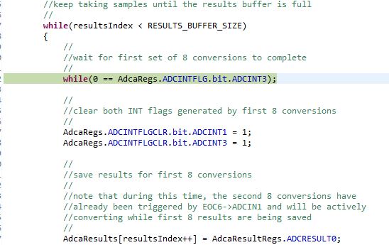
I then proceeded to check here and see if the value of my ADC interrupt flags is being set at all, since this is the reason why I seem to be sitting in this conditional forever:

But upon setting a break-point and stepping over these assignments, not even the value of the bit seems to be changing in the Expressions list.
Does anyone have any idea of what could be going on? This is sample code so I kind of expected it to be an easy victory for me.
Thanks,
-Adam

