This thread has been locked.

If you have a related question, please click the "Ask a related question" button in the top right corner. The newly created question will be automatically linked to this question.

Echo back through USB on F28377S

Other Parts Discussed in Thread: TMS320F28377S

Hi there,

I received an F28377S recently and am starting to tinker around with it. My ultimate goal is to have some data collected from an accelerometer output to a terminal window for me to capture while running an experiment.

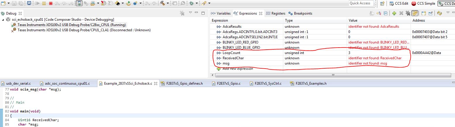
I have the ADC sampling and capturing fine so far, but want to now output this data onto a PuTTy terminal window. I decided that using the SCI echo back example should be a great place to start, so I loaded it onto the board. After seeing no welcome message print to the terminal, and LoopCount variable not incrementing when I pressed any keys in the terminal window, I figured something must be wrong on  my end. After a quick search on e2e, I found this post: that says to change the SCI pins from GPIO28 and 29 to 84 and 85.

After doing this, I still received nothing in the hyper terminal. A quick look at the data sheet showed that for my package (PZP), these pins should have been 85 and 86, instead of 84 and 85?


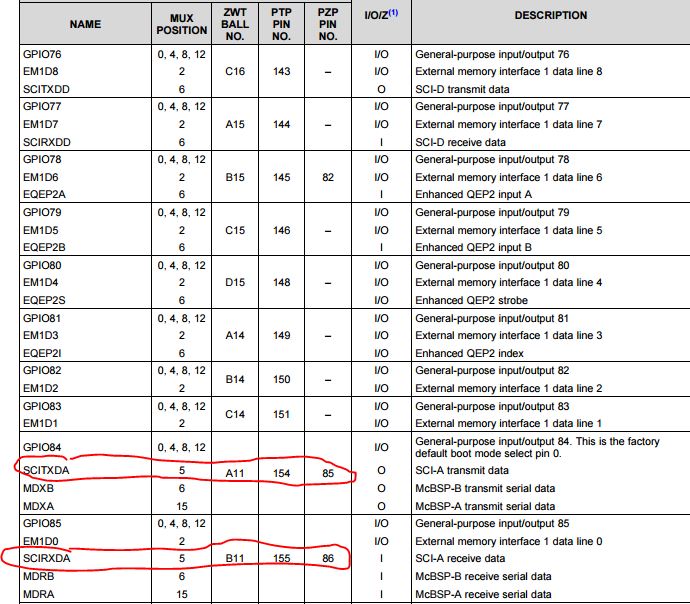
So I tried setting them to pins 85 and 86, and my LoopCount is now incrementing when I press a key in the terminal window, but there is no welcome text OR echo back.

GPIO_SetupPinMux(85, GPIO_MUX_CPU1, 5)

GPIO_SetupPinMux(85, GPIO_MUX_CPU1, 5)

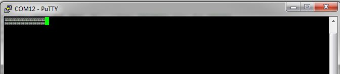
It seems as if the dev board is not transmitting anything at all to my terminal.

Any advice on what I'm doing wrong? My PuTTy is set up to the correct COM port and everythng, (9600 Baud, 8, 1, N, no flow control)

Thanks,

-Adam

  • I've looked through the code and checked the register settings and still can't seem to get this to work. Has anyone had a similar problem? I will post the code if that will help, but I haven't changed anything aside from what I mentioned above.
  • Adam,

    Sorry for the delayed response, to me it looks like there was a bit of confusion between GPIO number and pin number. Just to clear it up, on the PZP package GPIO84 connects to pin 85 and GPIO85 connects to pin 86(this was probably just a simple typo on the other post).

    And for debugging, lets start with the simple stuff.

    1. Your LoopCount is incrementing, that means you are at least receiving a character, can you look at the ReceivedChar variable and see if you are receiving the correct character or a garbage value?

    2. Are you positive that you are correctly configuring the GPIOs as input/output etc., I ask this because you added two lines of code above that both setup pin 85 "GPIO_SetupPinMux(85, GPIO_MUX_CPU1, 5)".

    3. To further debug this it would be helpful if you could attach an oscilloscope to the TX pin from the F28377s, this will help tell us if the issue is on the microcontroller side or the terminal side.

    3.1 Assuming the problem is on the microcontroller side I would suggest running in loopback mode(internal by setting LOOPBACKENA bit =1, or external loopback using a jumper wire). This should allow you to work out the bugs in your code, then you can switch to communicating with a remote terminal.

    Regards,
    Cody

  • Hi Cody,

    Thanks for your reply. Here is my code for setting up the SCI TX/RX pins:

      GPIO_SetupPinMux(85, GPIO_MUX_CPU1, 5);
    
      GPIO_SetupPinOptions(85, GPIO_OUTPUT, GPIO_ASYNC);
    
      GPIO_SetupPinMux(86, GPIO_MUX_CPU1, 5);
    
      GPIO_SetupPinOptions(86, GPIO_INPUT, GPIO_PUSHPULL);
    

    Which looks correct:

    PZP Pin 86 = GPIO 85 = SCIRXDA

    PZP Pin 85 = GPIO 84 = SCITXDA

    I added ReceivedChar but I never seem to get anything. In fact, CCS shows the following:

    I then set up the scope and probed the SCIRX pin (Pin 11 on U5), and got great signal readings from my key presses in the terminal window. However, notice above, that ReceivedChar never updates, and the SCITX pin has no activity on it at all.

    It seems that there is something askew on the controller side of things? Also, I took a look at the TRM and didn't see any mention of a LOOPBACKENA bit. Can you point me in the right direction to where this is in the manual, and what significance it has?

    Thanks!

    -Adam

  • Adam,

    I spelled the bit name wrong it's "LOOPBKENA", Using this bit allows you to internally connect the TX and RX pins of the SCI module, there by eliminating any hardware setup issues you may have. If you open the F28377s TRM go to  Table 18-7. "SCICCR Register Field Descriptions" bit 4. Hopefully this will allow you to test the configurations of your SCI receiver which seems to have some bugs.

    Your pin setup looks correct to me, and the fact that CCS can't find "RecievedChar" might point that you are not loading the correct code or that maybe there is a small spelling error in the variable name.

    Regards,
    Cody

  • Hi Cody,

    After digging around with the register tables and adding SciaRegs to my Expression list, I discovered that all of the data/code does seem to be working properly. When I press a key in my terminal, I see that value appear in SCIRXBUF.SAR as expected, and the character even gets placed into the SCITXBUF to be sent out.

    However, as I previously mentioned, I am never receiving anything on the transmit pin. I now believe that there is a problem with the way my transmit and receive pins are set up. Here they are again

       GPIO_SetupPinMux(85, GPIO_MUX_CPU1, 5);
       GPIO_SetupPinOptions(85, GPIO_OUTPUT, GPIO_ASYNC);
       GPIO_SetupPinMux(86, GPIO_MUX_CPU1, 5);
       GPIO_SetupPinOptions(86, GPIO_INPUT, GPIO_PUSHPULL);

    Now when I look in F287xS_Gpio.c, I notice this snippet in the comments, stating that an OUTPUT can never be ASYNC, only the input can.

    // GPIO_SetupPinOptions - Setup up the GPIO input/output options for the
    //                        specified pin.
    //                        The flags are a 16-bit mask produced by ORing
    //                        together options.
    //                        For input pins, the valid flags are:
    //                        GPIO_PULLUP  Enable pull-up
    //                        GPIO_INVERT  Enable input polarity inversion
    //                        GPIO_SYNC    Synchronize the input latch to PLLSYSCLK
    //                                     (default-you don't need to specify this)
    //                        GPIO_QUAL3   Use 3-sample qualification
    //                        GPIO_QUAL6   Use 6-sample qualification
    //                        GPIO_ASYNC   Do not use synchronization or
    //                                     qualification
    //                        (Note: only one of SYNC, QUAL3, QUAL6, or ASYNC is
    //                         allowed)
    //
    //                        For output pins, the valid flags are:
    //                        GPIO_OPENDRAIN   Output in open drain mode
    //                        GPIO_PULLUP      If open drain enabled, also enable
    //                                         the pull-up and the input
    //                                         qualification flags
    //                                        (SYNC/QUAL3/QUAL6/SYNC) listed above.

    Now this is where I need a little help, as this seems to be the root of my problem!! So close!

    Thanks,

    -Adam

  • Adam,

    are you using a controlCard? If so there is a UART ISO switch(sw1 if I remember correctly) Could you check the state of this switch?

    Hope it helps,

    Cody

  • Cody,

    Nope, I am just interfacing the dev board to my laptop via the included USB cable and PuTTY running on my laptop as well.
  • Adam,

    could you link me to the exact development board that you are using? I'll look and see if it has a similar jumper.

    Regards,
    Cody

  • Sure thing, its the TMS320F28377S LaunchPad development board. I'll take a look at the jumpers as well. Do you know where I can find the out of box firmware that came with the board? That program was sampling an ADC pin and outputting the result to CCSs terminal window, and may have a clue as to what I am doing wrong?

    Thanks again for your help!

    -Adam

  • Adam,

    The "out of box" example is included with controlSUITE under "development_kits->LAUNCHXL-F28377S->LaunchPadDemo".

    Regards,
    Cody

  • Hi Cody,

    Well, the OoB example is, of course, throwing errors with XDAIS and won't build. Come to find out, this is a known issue that others are having as well

    Link to problems with XDAIS and CCSv6

    Regardless of that, I feel like my problem *must* be somewhere in the pin muxing and/or configuration of these pins. To reiterate, I have them setup as such    

      GPIO_SetupPinMux(85, GPIO_MUX_CPU1, 5);

      GPIO_SetupPinOptions(85, GPIO_OUTPUT, ???????);

      GPIO_SetupPinMux(86, GPIO_MUX_CPU1, 5);

      GPIO_SetupPinOptions(86, GPIO_INPUT, GPIO_ASYNC);

    Now I see that I have the cpu parameter set to GPIO_MUX_CPU1. In the TRM, it shows that GPIO84 and 85 belong to MUX group 2. Seeing as how we're using MUX_CPU1 currently, maybe this is the problem? I'll give it a try and let you know, but I still don't know how to confgure the pins correctly (i.e open drain? Pull up?). I know the RX pin, 86, should be ASYNC since it should be able to handle an input at any giving time, so the output will need to be configured accordingly.

    Thanks,

    -Adam

  • Adam,

    I don't think that changing "GPIO_MUX_CPU1" will help, this should be set to whichever CPU is running the code( I assume you are using CPU1). Using "GPIO_SetupPinOptions(85,GPIO_OUTPUT, GPIO_PUSHPULL);" should work. Additionally using "GPIOSetupPinOptions(86, GPIO_INPUT, GPIO_ASYNC);"  for you RX pin is correct.

    Can you test the device with internal loop back enabled? This will help tell us if the SCI setup is correct, if its correct then we can explore the GPIO setup further.

    Regards,
    Cody

    CORRECTION: The above is incorrect, see correction below.

    Using "GPIO_SetupPinOptions(85 84,GPIO_OUTPUT, GPIO_PUSHPULL);" should work. Additionally using "GPIOSetupPinOptions(86 85, GPIO_INPUT, GPIO_ASYNC);"  for you RX pin is correct.

  • Hi Cody,

    I set the loopback to enabled and the program seems to run. I fed it a test message of 'Hello' and stepped through the code and saw that the messages appeared in the transmit buffer SCITXBUFF, and then appeared in the receive emulation buffer and then the receive buffer (SCIRXEMU and SCIRXBUF respectively).

    The LoopCount variable also incremented as expected, so it seems that with a hard-coded message, the loopback is working properly. Now the challenge is to get the GPIO working so I can effectively make my echo-back. What are the next steps we should take in debugging this?

    Thanks,
    -Adam
  • Adam,

    that is great to hear! Since pins 84 and 85 are not pinned out to a header, one option would be to switch to SCIC or SCIB(only for debug, you will need to switch back to SCIA once you have everything working). Using SCIC/B will allow you to use a jumper wire to connect TX and RX, this means you can verify/debug your GPIO configurations. Note the controlSuite examples should work without error, look at a few of those examples.


    Regards,
    Cody

  • Hey Cody,

    I changed the baud rate from the previous 9600 baud to the baud rate from the Out of Box software (115200) in the code, and I am now getting *something* on the terminal when I press keys. It is echo-ing back, just echo-ing back garbage values.

    This is a step in the right direction! However, when I press 'a' on my keyboard, I am expecting to see 'a' output on my console and see the decimal representation of 'a' in SciaRegs. This is starting to seem more and more like a baud rate issue...maybe since I am using SCI-A and the FTDI chip, I am using the external oscillator rather than the oscillator used for SCI-B? I'll try and re-do the calcs for SCIHBAUD and SCILBAUD and get back to you using the FTDI oscillator's frequency

    Happy Friday!
    -Adam
  • Adam,

    This does sound like it could be a baud rate issue.

    I am not sure I understand your question, but if you want to check what your clockrate is you should use XCLKOUT. The use of XCLKOUT is detailed in the Technical Reference Manual section 2.7.4. XCLKOUT is just a way to bring clock sources(PLLSYSCLK,  PLLRAWCLK, SYSCLK, etc.) out to a pin for observation.

    Regards,

    Cody

  • Hi Cody,

    I looked at the TRM and configured GPIO73 to output XCLKOUT as follows:

    EALLOW;
    ClkCfgRegs.CLKSRCCTL3.bit.XCLKOUTSEL = 0; // Should set clock src to SYSCLK (200MHz)
    ClkCfgRegs.XCLKOUTDIVSEL.bit.XCLKOUTDIV = 0; // Set divider to 1
    GpioCtrlRegs.GPCMUX1.bit.GPIO73 = 3; // GPIO73 -> XTALOUT
    EDIS;

    This should set everything up to run according to this code that sets the SYSCLK to be 200MHz. When I probe it with a scope, I am seeing 100MHz; could this be because of the InitSysPll method here having a parameter of PLLCLK_BY_2?

        //
        //  PLLSYSCLK = (XTAL_OSC) * (IMULT + FMULT) / (PLLSYSCLKDIV)
        //
    #ifdef _LAUNCHXL_F28377S
        InitSysPll(XTAL_OSC,IMULT_40,FMULT_0,PLLCLK_BY_2);

    Also, strangely enough when I configure the GPIO in this manner:

       GPIO_SetupPinMux(85, GPIO_MUX_CPU1, 5);
       GPIO_SetupPinOptions(85, GPIO_OUTPUT, GPIO_PULLUP);
       GPIO_SetupPinMux(86, GPIO_MUX_CPU1, 5);
       GPIO_SetupPinOptions(86, GPIO_INPUT, GPIO_ASYNC);

    I do NOT get any kind of ech-back in my terminal, not even garbage. But when I configure the GPIO in the same way as in Example_F28377xLaunchPadDemo, I DO get garbage echo'd back with a baud rate of 115200 as opposed to the 9600 baud as calculated in the example with the 200MHz system clock (which should be the case since this is a 200MHz processor...). This is how they do it in that example:

    void scia_init()
    {
    
        // Note: Clocks were turned on to the SCIA peripheral
        // in the InitSysCtrl() function
    
     	SciaRegs.SCICCR.all =0x0007;   // 1 stop bit,  No loopback
                                       // No parity,8 char bits,
                                       // async mode, idle-line protocol
    	SciaRegs.SCICTL1.all =0x0003;  // enable TX, RX, internal SCICLK,
                                       // Disable RX ERR, SLEEP, TXWAKE
    
    	SciaRegs.SCICTL2.bit.TXINTENA =1;
    	SciaRegs.SCICTL2.bit.RXBKINTENA =1;
    
    	SciaRegs.SCIHBAUD.all    =0x0000;  // 115200 baud @LSPCLK = 22.5MHz (90 MHz SYSCLK).
            SciaRegs.SCILBAUD.all    =53;
    
    	SciaRegs.SCICTL1.all =0x0023;  // Relinquish SCI from Reset
      
        return;
    }
        // For this example, only init the pins for the SCI-A port.
        EALLOW;
        GpioCtrlRegs.GPCMUX2.bit.GPIO84 = 1;
        GpioCtrlRegs.GPCMUX2.bit.GPIO85 = 1;
        GpioCtrlRegs.GPCGMUX2.bit.GPIO84 = 1;
        GpioCtrlRegs.GPCGMUX2.bit.GPIO85 = 1;
        EDIS;

    So ultimately there are two things behaving strangely here: my SYSCLK output being 100MHz vs the expected 200MHz, my GPIO not behaving as expected when using the built in helper methods from TI's own code (may be due to baud rate which relates back to the SYSCLK).

    Any ideas?

    Thanks,

    -Adam

  • Hey Cody,

    So I figured out one of my questions. There is a confusing snippet in the code comments that states the first parameter passed into GPIO_SetupPinMux and GPIO_SetupPinOptions is a PIN, when in fact it is still the GPIO number!! I found this out by stepping through the code and looking at the register values and noticed it was setting GPIO85 and 86 instead of 84 and 85.

       GPIO_SetupPinMux(84, GPIO_MUX_CPU1, 5);	//Sets GPCGMUX2 bits for GPIO84
       GPIO_SetupPinOptions(84, GPIO_OUTPUT, GPIO_PULLUP);
       GPIO_SetupPinMux(85, GPIO_MUX_CPU1, 5);
       GPIO_SetupPinOptions(85, GPIO_INPUT, GPIO_ASYNC);

    Making these changes, I am now seeing garbage on my terminal output at the specified 9600 baud in the code. Getting closer now, and the only thing I can think of now is something funny going on with the baud rates and the SCIHBAUD and SCILBAUD.

    This is what I'm seeing on the terminal output, no matter what characters are passed from being hard-coded or pressed on the keyboard:

  • My mistake for recommending the wrong GPIO setup, it goes to show how easy it is to gloss over the code and miss small details. I am glad you solved that!

    For the second issue make sure that the following formula is used "SCI Baud = LSPCLK / ((BRR + 1) *8)" to calculate the baud rate. More details about this are in section 18.14.2.3 of the Technical Reference Manual.

    Regards,
    Cody

  • Hey Cody,

    Well, after all this time I've figured it out. This is the culprit:

    #ifdef _LAUNCHXL_F28377S
        InitSysPll(XTAL_OSC,IMULT_40,FMULT_0,PLLCLK_BY_2);
    #else
        InitSysPll(XTAL_OSC,IMULT_20,FMULT_0,PLLCLK_BY_2);
    #endif

    I dont know WHERE this is defined, but I assumed that I am using the LaunchXL F28377S, it would hop into that definition of the function call.

    NOPE.

    I changed the #else statement to have an IMULT of 40 instead of 20, and that was it. Problem solved!!!! This explains why I was seeing the 100MHz clock output instead of the 200MHz clock output on GPIO73!

  • Great! I am glad to hear it. The smallest mistakes are usually the hardest to find. Feel free to mark one or more posts as answers to the thread, it will help people in the future!

    Regards,
    Cody