Other Parts Discussed in Thread: CONTROLSUITE
Hello,
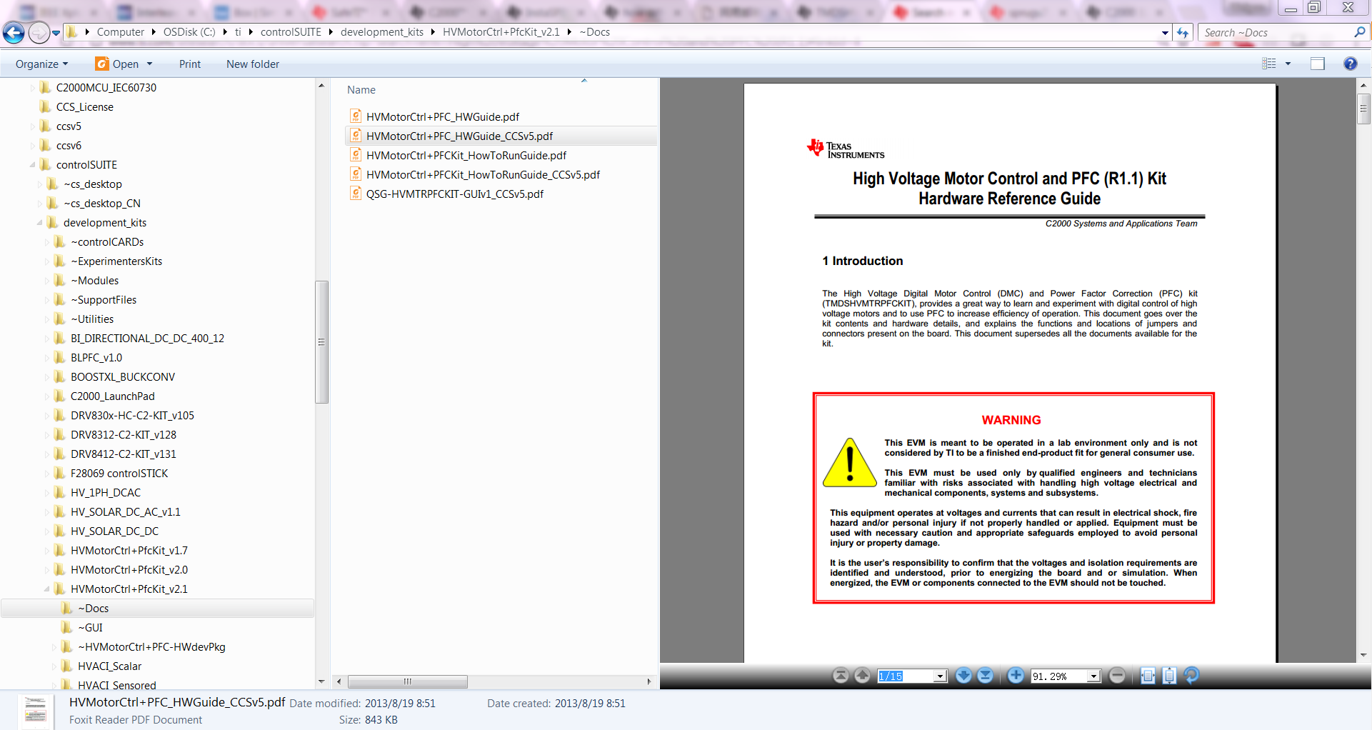
I have questions about the hardware set up for TMDSHVMTRPFCKIT section 2.1 item 3 on pg5,
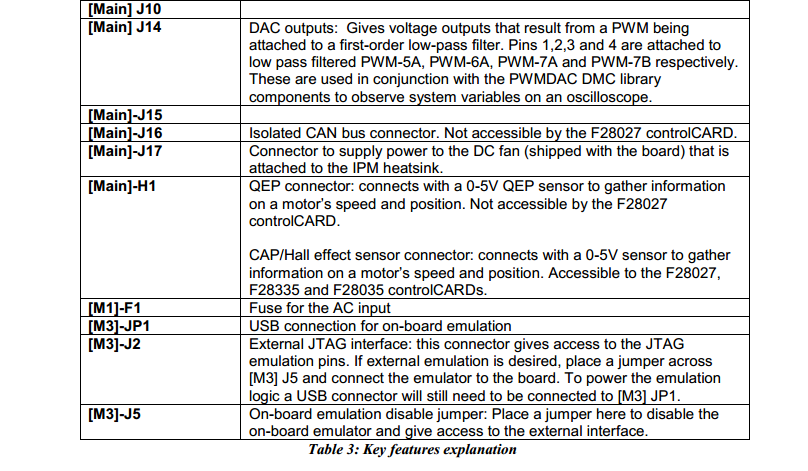
- M3]-J4 is populated {WHAT IS POPULATED? is j4 the USB Cable?}
- Main]-J11,J12 & J13 are populated with jumper b/w 1 and the middle pin { WHAT IS B/W 1?, WHAT IS MIDDLE PIN? J11,J12 & J13 are not labeled, I'm assuming they are the 3 phases, right?}
- [Main]-J3,J4 & J5, are populated; {FOUND THEM, POPULATED WITH WHAT?}
- [Main]-J2 is populated with a jumper b/w bridge and the middle pin {THIS IS NOT CLEAR, COULD SOMEONE ELABORATE ON THIS? WHAT IS jumper b/w bridge? MIDDLE PIN FROM WHERE?}
- Make sure that [M6]-J6,J7,J8 ; [Main]-J9 and [M3]-J1,J3,J5 are not populated {COULD NOT FIND J6,J7,J8?, J9 DOES NOT EXIST? M3J1 &JM3J3 DO NOT EXIST?}
- Ensure Banana cable b/w [Main]-BS1 and [Main]-BS5 is installed {this is understandable}
who wrote this? pictures would be great.
there is also a cable coming from the bottom of the kit, from the fan, where does that go?
Jose