This thread has been locked.

If you have a related question, please click the "Ask a related question" button in the top right corner. The newly created question will be automatically linked to this question.

TMS320F28377S: F28377S Trying to boot to flash

Part Number: TMS320F28377S
Other Parts Discussed in Thread: CONTROLSUITE

I've ported a working F28027 program to F28377S and having a bit of trouble getting it to boot from flash.  I'm following SPRA958L as far as I can tell since it doesn't mention F28377S yet.


In my linker command file, I have the following:

MEMORY
    BEGIN_FLASH :   origin = 0x00080000  length = 0x00000002  /* boot rom jumps to here */

SECTIONS
    codestart: >    BEGIN_FLASH, PAGE = 0


In codestart.asm, I have the usual:

    .ref _c_int00
    .sect "codestart"
    LB _c_int00     ;Branch to start of C initialization

The linker then places c_int00 at 0x80cb0:

******************************************************************************
             TMS320C2000 Linker PC v15.12.3                    
******************************************************************************
>> Linked Fri Dec 16 12:18:00 2016

OUTPUT FILE NAME:   <rgb_f28377.out>
ENTRY POINT SYMBOL: "_c_int00"  address: 00080cb0

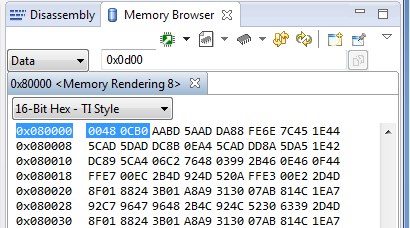
However, when I flash the program in CCS and look at 0x0008_0000, I don't quite see the right address for c_int00:

Am I missing something?

Thanks, dave

  • The picture of the debugger didn't post above.  Here it is showing the address 0x004b_0cb0 written to 0x0008_0000:

  • Hi,

    I see the correct value (0x80CB0) at 0x80000 address location. Are you running it standalone or with CCS connected?

    Regards,
    Vivek Singh
  • Yes, I'm using CCS to write the program into flash. I can disconnect the launchpad from the PC, then reattach and view 0x80000 and still see 0x0048_0cb0.  Of course, when I try to run the program without CCS it never gets to c_int00.

    Thanks, dave

  • Have you checked the BOOTMODE pin setting to make sure these have correct value for BOOT to Flash mode?
  • If you're referring to the S1 switch positions, yes - they are still in the original taped down (ON) positions.

    I looked at the C28 instruction set PDF, and it explained the difference in the address.  The LB instruction is 0x0040_0000 plus a 22-bit address, so that's okay. It appears that the program is written to flash correctly, because I can connect the board to the PC, attach the debugger and the program will run without loading it.  I just haven't figured out why it doesn't branch to 0x0008_0000 when running from flash.

  • So I'm still struggling with this.  I've tried compiling and running the "blinky" example for both RAM and FLASH, and it works fine.  When flashed, and the board is powered up without CCS, the program runs without problems.  So I know it's not the board, or board settings.

    I then made a copy of the blinky project and substituted in my code, so that I'm using all the default build flags, .cmd files, startup assembly, project settings, etc.  There are no compile/link warnings or errors. It still does not run without CCS.  When powered up, the CPU never makes it to main().  If I attach CCS the PC is sitting at 0x3ff16a (reset).  I can then assembly step the PC and it will eventually branch to 0x80000, then to _c_int00, and jump to main().

    Next, thinking that maybe control was making it to main() and then aborting back to reset, I tried two experiments:

    1) I changed the LB _c_int00 instruction in codestart.asm to LB 0x80000 (i.e. branch to self). With this, the PC is still at 0x3ff16a when CCS is attached.

    2) I put a while(1) {} at the top of main().  PC still at 0x3ff16a.

    So it seems that it never jumps to 0x80000 by itself, and it's not clear why.  I would suspect my code, but it doesn't seem to be even executing.  I'm not sure what to do next...

  • Please check the value of NMISHDFLG (0x7066) register after running in standalone and then connecting to CCS. Also if possible check the status of XRSn pin on board when running in standalone mode.

    Regards,

    Vivek Singh

  • Thanks Vivek!

    The NMISHDFLG (0x7066) register is zero.  The XRSn pin is the RESET pin connected to S3, if I interpreted the schematic correctly.  Of the S3 pushbutton pins, the one on right is connected to ground, and the one on the left is 3.26V.


    Thanks, dave

  • Hi Dave,

    Did you probe the XRSn pin while running the device in standalone mode?

    Vivek Singh
  • Well, it was while the board was attached to CCS and in the debugger. If I just attach the board to USB, the voltage of XRSn is 3.20V.

    Thanks! dave
  • Are you checking this on scope?
  • Hi Vivek, thanks for checking in on this!

    I've been off doing other things, but am now at a point where I have to get it booting from flash.  I don't have a scope, and I'm not sure where I would look since it never branches to my code.  Perhaps I could borrow one.

    If you would like to take a look, I would greatly appreciate the help.  I have all the source code and CCS project files in git here:

    https://github.com/leddave/f28377_color_organ

    This is an awesome little program - it is a 20 channel (10 channel stereo) color organ.  It uses the ADC to sample L/R channels at 44Khz, runs FPU FFTs, reduces the FFT bins to 10 channels per L/R, then creates a display and uses GPIOs to bit-bang color data to 4 strings of either WS2811 or WS2812 RGB LEDs. Very impressive to watch!

    If you can't take a look, I would appreciate pointers on where to look.

    Thanks, dave

  • I solved the problem. It was actually booting, then the watchdog would expire and reset the board in an infinite loop. Part of the problem was the #define FLASH vs. _FLASH that is used in ControlSuite. The other part was the watchdog not getting disabled, and the init flash routines not being in RAM when called.