This thread has been locked.

If you have a related question, please click the "Ask a related question" button in the top right corner. The newly created question will be automatically linked to this question.

TMS320F28027: Lab 5a non-uniform waveforms

Part Number: TMS320F28027
Other Parts Discussed in Thread: TIDA-00643,

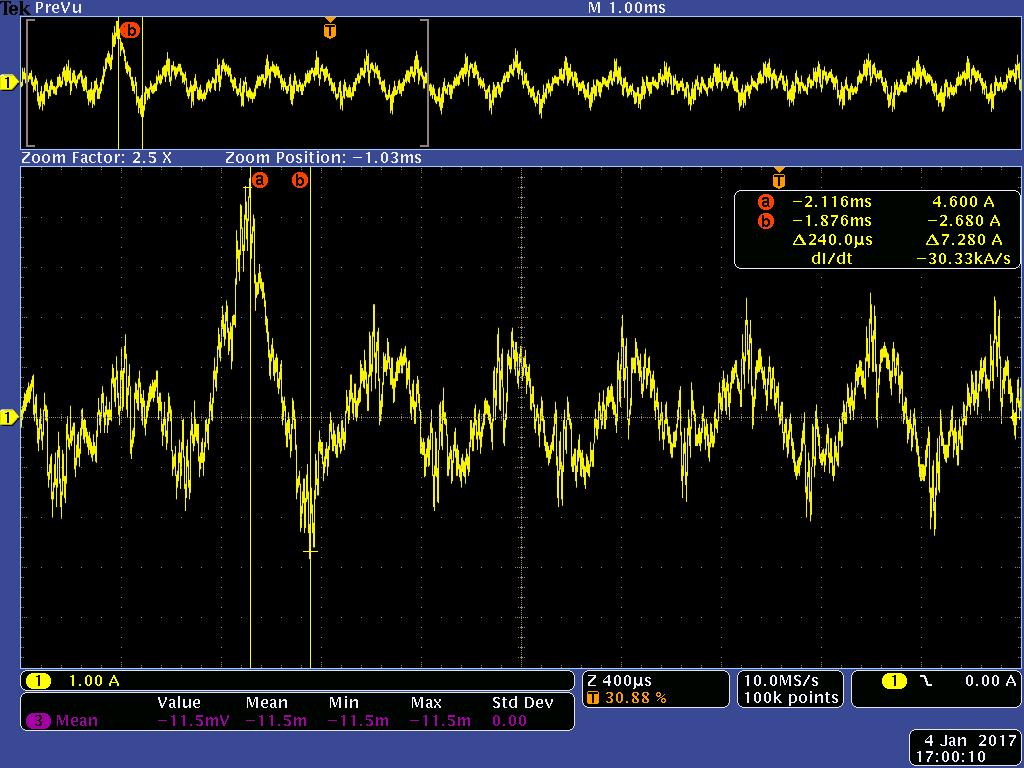
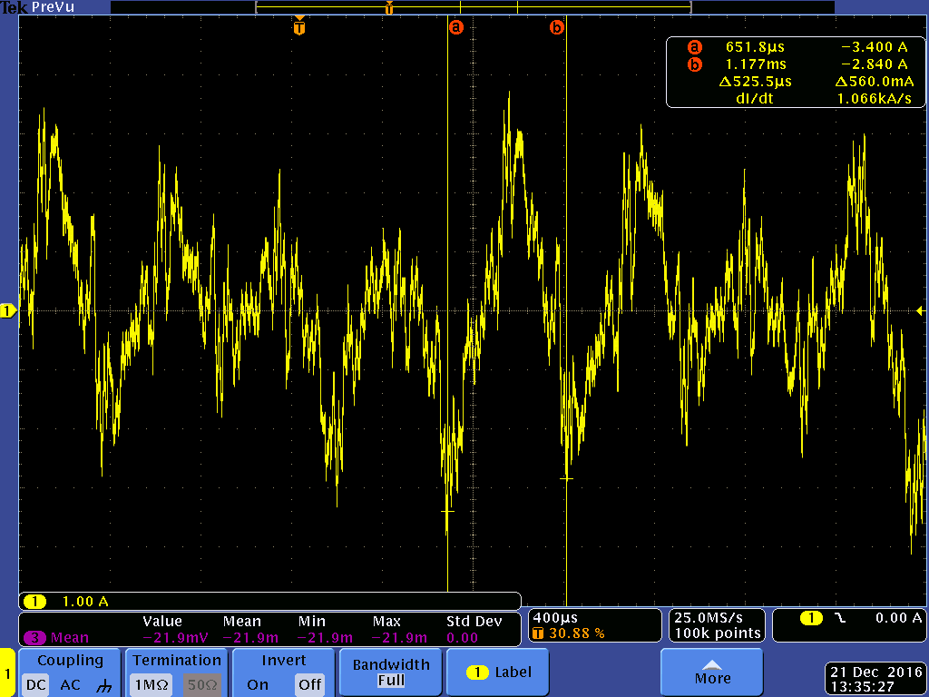
I've been testing a custom TIDA-00643 design with a number of hobby motors and have come across a motor that is difficult to tune the current controller for.  The waveforms from lab 5a for this particular motor are not only very noisy but the peaks in the phase current are very uneven.  This motor is a little different than the others in that it has more poles (12 pairs) and is more of a "pancake" style motor with slightly higher resistance and inductance than the others I've tried (Rs=.111, Ls=41uH).  I've tried reducing the Kp gains in half from the ROM defaults and also the Ki from defaults but end up with almost identical waveforms regardless.  I'm wondering if there are some other options I should consider changing in my user.h?
 6472.user.h   

  • 1. Often, the hobby motor is a low inductance motor, please use lab02c to identify motor parameters correctly.
    2. Please use higher pwm frequency for this low inductnace, high speed motor, it's better to use 30KHz~60KHz.
    3. You need to adjust Kp,Ki for speed and current PI regulator. Reduce the Kp and Ki for speed PI first.
    4. Change USER_SPEED_POLE_rps from 100 to 300 in user.h
  • 1. lab02c is able to identify motor parameters that are very close to values I've found using and LCR meter.  I have been able to test other motors with much smaller Ls/Rs values than this motor previously.
    2. PWM frequency is already at 45kHz,  I don't believe this to be the issue if I can run with motors of significantly smaller Ls/Rs values as stated above.

    3. I have already tried to adjust these values but haven't found values that smooth out the irregular patterns in the current waveforms.

    4. What exactly does USER_SPEED_POLE_rps change?  User.h and spruhj1.pdf only describe it as the software pole location for the speed control filter and is marked as "do not change".  What effect does this value have and what are acceptable ranges for this value?

  • A further update to what I've found in testing.

    Changing USER_SPEED_POLE_rps has no effect on the current waveforms. Isn't this parameter used for the speed controller, or is it used by the current controller as well?

    While looking through the motoware_selecting_user_variables spreadsheet I realized that while this motor runs at the lowest mechanical RPM rate of all the ones I've tested, it's electrical frequency is the highest because of the high pole count (12 pairs) and the fact that it's on a 6S supply (25V) which gives a 1915Hz electrical frequency with the others being in the <1500Hz range. Increasing the PWM frequency to 60kHz as a result increases the current controller to 20kHz and now the current waveforms are much more uniform and the amplitude has dropped from >+/-3A to less than +/-1A. I did not consider this before since in other posts I've read that the current controller is usually fine if the frequency > 7x the max electrical frequency and motor identification worked just fine.

    I'm wondering if more improvement can be had and as such would changing USER_NUM_PWM_TICKS_PER_ISR_TICK from 3 to 2 to get the controller up to 30kHz would be a good idea? I'm thinking there has to be a point where the computational load might be too much for the tms320f28027 to handle at some point?
  • Chris posted some information here regarding MIPS usage per increase in sampling frequency you may find helpful

    e2e.ti.com/.../1225180

    Sean
  • Thanks Sean.  Good to know that 20kHz is the limit for this part.  Is there anything else I can try in the user.h settings?  Not sure if switching parts makes sense at this point.  The waveforms are better but I occasionally see a spike in the phase current from time to time that I'm not comfortable with.