Part Number: TMS320F2808
Hello,
I have been developing sine wave modulator for three phase voltage source inverter
on TMS320F2808 DSP. I have been using CCS v6 for debugging (especially the Graph
tool). I have developed the code which is intended for desired sine wave generation (please
see the attachment). My problem is that the sine wave produced by this code is OK only
at some frequencies (I watch the output sine wave in Graph tool). Now I don't know whether
the problem is in my code or in graph in CCS. Please can anybody look at my code and evaluate
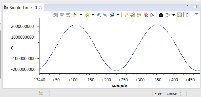
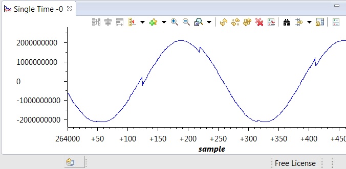
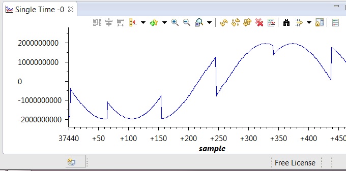
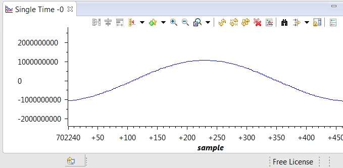
whether it is allright? Below are the graphs for:
1. 50 Hz ~ 32767
2. 49 Hz ~ 32200
3. 45 Hz ~ 30000
4. 25 Hz ~ 16384
Thanks in advance.
// index, 16 bits, 0-65535
static unsigned short index1 = 0;
static unsigned short index2 = 0;
// desired output frequency, 50 Hz ~ 32767
static unsigned short frequency = 32767;
// temporary variable
static short temp = 0;


// table with sine values in Q1.15
// table covers full period <0, 2*pi> with 129 values (due to linear interpolation)
// angle step in table (2*pi)/128 ~ 2.8 °
// normalized angle step (2*pi)/128*1/(2*pi)*65536 = 512
static short sine_table[] = {
	     0,   1608,   3212,   4808,
	  6393,   7962,   9512,  11039,
	 12539,  14010,  15446,  16846,
	 18204,  19519,  20787,  22005,
	 23170,  24279,  25329,  26319,
	 27245,  28105,  28898,  29621,
	 30273,  30852,  31356,  31785,
	 32137,  32412,  32609,  32728,
	 32767,  32728,  32609,  32412,
	 32137,  31785,  31356,  30852,
	 30273,  29621,  28898,  28105,
	 27245,  26319,  25329,  24279,
	 23170,  22005,  20787,  19519,
	 18204,  16846,  15446,  14010,
	 12539,  11039,   9512,   7962,
	  6393,   4808,   3212,   1608,
	     0,  -1608,  -3212,  -4808,
	 -6393,  -7962,  -9512, -11039,
	-12539, -14010, -15446, -16846,
	-18204, -19519, -20787, -22005,
	-23170, -24279, -25329, -26319,
	-27245, -28105, -28898, -29621,
	-30273, -30852, -31356, -31785,
	-32137, -32412, -32609, -32728,
	-32767, -32728, -32609, -32412,
	-32137, -31785, -31356, -30852,
	-30273, -29621, -28898, -28105,
	-27245, -26319, -25329, -24279,
	-23170, -22005, -20787, -19519,
	-18204, -16846, -15446, -14010,
	-12539, -11039,  -9512,  -7962,
	 -6393,  -4808,  -3212,  -1608,
	 0
};

// angle step for desire output frequency
static unsigned short delta_phase = 0;
// phase accumulator
static unsigned short phase = 0;
// output sine wave
static short sine_wave = 0;


// angle step for desired output frequency which is set by frequency variable
// for one interrupt with frequency fs the angle step in radians is 2*pi*f/fs
// so the normalized angle step is f/fs*65536
// for desired 50 Hz and fs=12000 Hz: 50/12000*65536 = 273
// 50 Hz is set as 32 767
delta_phase = ((((unsigned long)frequency)*273) >> 15);


// increment phase accumulator with angle step
phase += delta_phase;


// "low" index
// phase to index conversion
// 128 values in table so only 7 highest bits set the index
// phase accumulator is 16 bit so >> 9
index1 = phase >> 9;
// "high" index
index2 = index1 + 1;

// retrieve the sine value from the table
// linear interpolation in the sine values table
temp = (*(sine_table + index2) - *(sine_table + index1));
// low 9 bits of the phase accumulator are "fractional" so & 0x1FF
// "full" angle step in table is 512 so >> 9
temp = (short)(((long)temp)*((phase & 0x1FF) >> 9));
temp += *(sine_table + index1);
// voltage to frequency ratio
sine_wave = (((long)frequency*temp) >> 15);