


Other Parts Discussed in Thread: CONTROLSUITE, MAX232
Tool/software: Code Composer Studio
Hi
I uesd ControlSUITE example code, 2837xDSci_echoback.c, to send the integers or chars, but the terminal always got the garbage signals from controlCard.
The SCI communication is through RS232 to send and receive data.
The hardware setup is
DB9 PIN2(Rx) -> GPIO29(Tx, PIN 78)
PIN3(Tx) -> GPIO28(Rx, PIN 76)
PIN5(GND) -> GND
And here is my main code for sending chars.
// Included Files
//
#include "F28x_Project.h"

//
// Globals
//
Uint16 LoopCount;
Uint16 msg1;
//
// Function Prototypes
//
void scia_echoback_init(void);
void scia_fifo_init(void);
void scia_xmit(int a);
void scia_msg(char *msg);

//
// Main
//
void main(void)
{
    Uint16 ReceivedChar;
    char *msg;
//
// Step 1. Initialize System Control:
// PLL, WatchDog, enable Peripheral Clocks
// This example function is found in the F2837xD_SysCtrl.c file.
//
   InitSysCtrl();

//
// Step 2. Initialize GPIO:
// This example function is found in the F2837xD_Gpio.c file and
// illustrates how to set the GPIO to it's default state.
//
   InitGpio();

//
// For this example, only init the pins for the SCI-A port.
//  GPIO_SetupPinMux() - Sets the GPxMUX1/2 and GPyMUX1/2 register bits
//  GPIO_SetupPinOptions() - Sets the direction and configuration of the GPIOS
// These functions are found in the F2837xD_Gpio.c file.
//
   GPIO_SetupPinMux(28, GPIO_MUX_CPU1, 1);
   GPIO_SetupPinOptions(28, GPIO_INPUT, GPIO_PUSHPULL);
   GPIO_SetupPinMux(29, GPIO_MUX_CPU1, 1);
   GPIO_SetupPinOptions(29, GPIO_OUTPUT, GPIO_ASYNC);

//
// Step 3. Clear all __interrupts and initialize PIE vector table:
// Disable CPU __interrupts
//
   DINT;

//
// Initialize PIE control registers to their default state.
// The default state is all PIE __interrupts disabled and flags
// are cleared.
// This function is found in the F2837xD_PieCtrl.c file.
//
   InitPieCtrl();

//
// Disable CPU __interrupts and clear all CPU __interrupt flags:
//
   IER = 0x0000;
   IFR = 0x0000;

//
// Initialize the PIE vector table with pointers to the shell Interrupt
// Service Routines (ISR).
// This will populate the entire table, even if the __interrupt
// is not used in this example.  This is useful for debug purposes.
// The shell ISR routines are found in F2837xD_DefaultIsr.c.
// This function is found in F2837xD_PieVect.c.
//
   InitPieVectTable();

//
// Step 4. User specific code:
//
   LoopCount = 0;

   scia_fifo_init();       // Initialize the SCI FIFO
   scia_echoback_init();   // Initialize SCI for echoback

   msg = "\r\n\n\nHello World!\0";
   scia_msg(msg);

   msg = "\r\nYou will enter a character, and the DSP will echo it back! \n\0";
   scia_msg(msg);


   for(;;)
   {
       msg = "\r\nEnter a character: \0";
       scia_msg(msg);

       //
       // Wait for inc character
       //
       while(SciaRegs.SCIFFRX.bit.RXFFST == 0) { } // wait for empty state

       //
       // Get character
       //
       ReceivedChar = SciaRegs.SCIRXBUF.all;

       //
       // Echo character back
       //
       msg = "  You sent: \0";
       scia_msg(msg);
       scia_xmit(ReceivedChar);

       LoopCount++;
   }
}

//
//  scia_echoback_init - Test 1,SCIA  DLB, 8-bit word, baud rate 0x000F,
//                       default, 1 STOP bit, no parity
//
void scia_echoback_init()
{
    //
    // Note: Clocks were turned on to the SCIA peripheral
    // in the InitSysCtrl() function
    //

    SciaRegs.SCICCR.all = 0x0007;   // 1 stop bit,  No loopback
                                    // No parity,8 char bits,
                                    // async mode, idle-line protocol
    SciaRegs.SCICTL1.all = 0x0003;  // enable TX, RX, internal SCICLK,
                                    // Disable RX ERR, SLEEP, TXWAKE
    SciaRegs.SCICTL2.all = 0x0003;
    SciaRegs.SCICTL2.bit.TXINTENA = 1;
    SciaRegs.SCICTL2.bit.RXBKINTENA = 1;

    //
    // SCIA at 9600 baud
    // @LSPCLK = 50 MHz (200 MHz SYSCLK) HBAUD = 0x02 and LBAUD = 0x8B.
    // @LSPCLK = 30 MHz (120 MHz SYSCLK) HBAUD = 0x01 and LBAUD = 0x86.
    //
    SciaRegs.SCIHBAUD.all = 0x0002;
    SciaRegs.SCILBAUD.all = 0x008B;

    SciaRegs.SCICTL1.all = 0x0023;  // Relinquish SCI from Reset
}

//
// scia_xmit - Transmit a character from the SCI
//
void scia_xmit(int a)
{
    while (SciaRegs.SCIFFTX.bit.TXFFST != 0) {}
    SciaRegs.SCITXBUF.all =a;
}

//
// scia_msg - Transmit message via SCIA
//
void scia_msg(char * msg)
{
    int i;
    i = 0;
    while(msg[i] != '\0')
    {
        scia_xmit(msg[i]);
        i++;
    }
}

//
// scia_fifo_init - Initialize the SCI FIFO
//
void scia_fifo_init()
{
    SciaRegs.SCIFFTX.all = 0xE040;
    SciaRegs.SCIFFRX.all = 0x2044;
    SciaRegs.SCIFFCT.all = 0x0;
}

//
// End of file
//
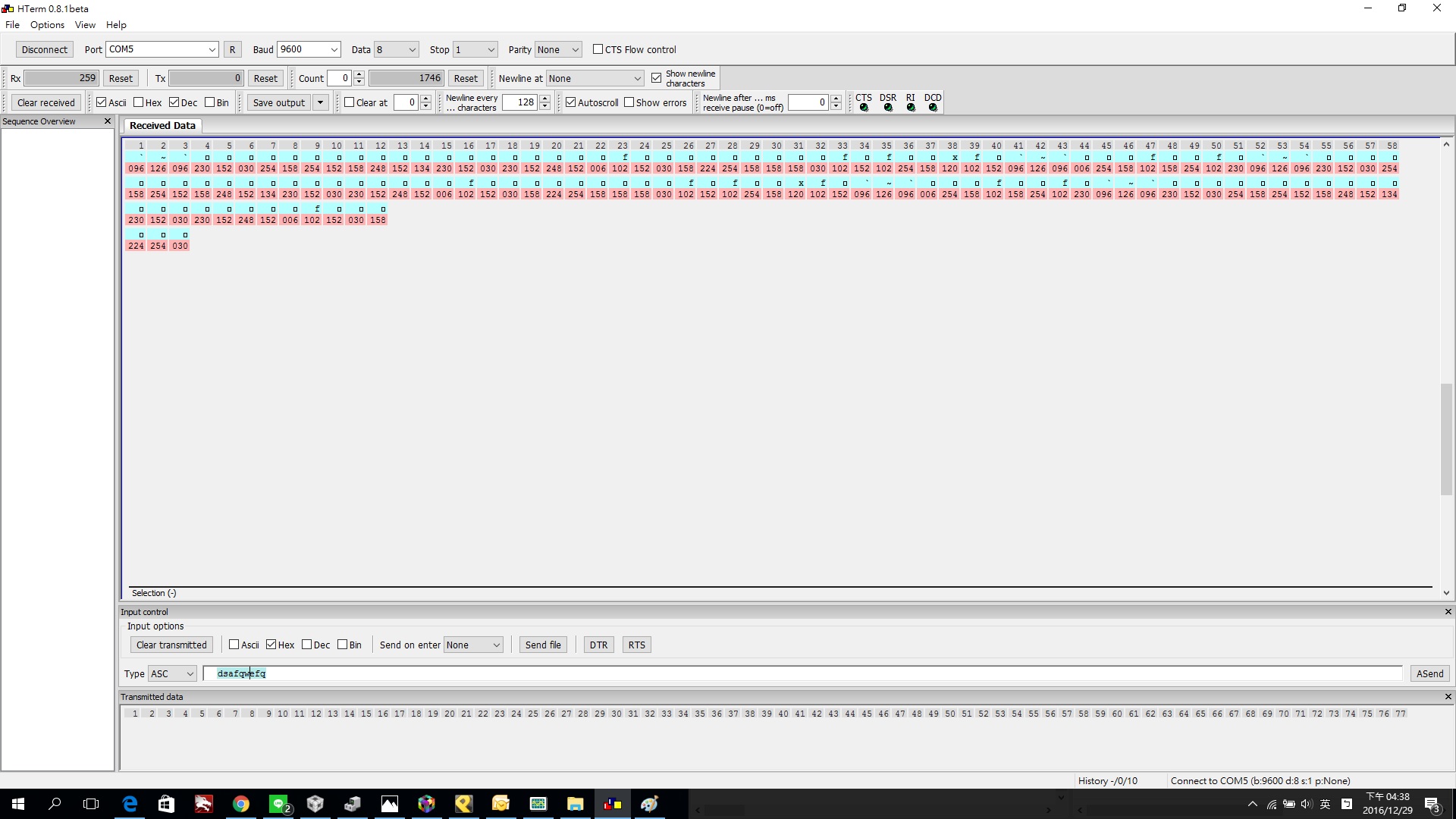
After debugging and executing, I get the garbage signals with controlcard.
There is the same result when sending the integers number loop from f28377, others setup doesn't change.
   for(;;)
   {
       msg1 = 10;
       scia_xmit(msg1);
       LoopCount++;
   }
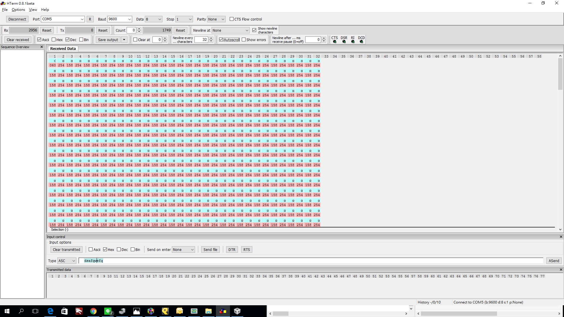
Does there anything wrong with my code or hardware setup?
Thanks
