This thread has been locked.

If you have a related question, please click the "Ask a related question" button in the top right corner. The newly created question will be automatically linked to this question.

CCS/TMS320F28069: ADC oscillation

Part Number: TMS320F28069


Tool/software: Code Composer Studio

I am using Experimenter Kit with F28069 control card for reading 11 analog signals, coming from current and voltage sensors. For channels A (0 to 3) and B (0 to 3) I have no problems in the readings, an oscillation around 5 bits appears for a stable signal.

The problem occurs when reading channels A (4 to 7) and B (4 to 7), using the same signal applied in the previous channels, the oscillation passes to 30 to 50 bits, with peaks of 100 bits.

Does anyone know if I need to do any additional setup on Piccolo?

Thanks,

  • Hi Progol,

    How frequently are you sampling the channels, and in what order?

    Is the same signal always connected to each of the A0 - A7 and B0 - B7 channels, or do you move the connection and observe the results one at a time?

    Is the oscillation visible on the ADC pins via an oscilloscope?
  • Hello,

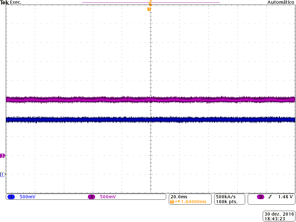
    I have an oscilloscope image, on channel 1 the signal is sampled in the piccolo and it becomes noisy, channel 3 shows the signal that is sampled in the piccolo in the normal way.

    In the next image using the GUI composer, I read the above signals on the oscilloscope, you can see some peaks in the reading of the signal that exceed 50 bits, while in the right image the oscillation is around 4 bits.

    In this case, I use channels A6 (noisy signal) and B2 (good signal), if I reverse the signals the noise repeats on channel A6.

    Thanks,

  • Hi Prigol,

    This does seem to be an issue with the ADC, since nothing is showing up on the external scope capture.

    -Are you sure the ADC is clocked at 45MHz and not 90MHz?
    -Per the errata document (sprz342k) there can be an issue with the first ADC conversion in a sequence of ADC conversions if non-overlap mode is not enabled. When you sample the A channel, is it the first in a series of conversions (maybe just an A channel and a B channel) or is it sampled on its own? Is the non-overlap mode enabled for the ADC?
    -What R and/or C is physically on each of these ADC pins? A large series R can prevent the ADC from correctly charging its S+H capacitor in the allocated S+H window.
    -The samples with errors seem somewhat evenly spaced. Is anything else going on in the system at the same time the ADC is sampling? Maybe an ePWM or communications interface that is toggling some GPIOs while the ADC is converting. If so, are these GPIOs physically close to the ADC channels which are seeing the error?
  • Thanks for the quick return, as I am a beginner with the Piccolo family, I will check the various pieces of information passed on to you, as I was not thinking about these possibilities.

    As soon as I have analyzed, return with the results,

    For now thank you very much.