Part Number: TMS320F28069F
I am laying out a custom motor driver board and I have two questions.
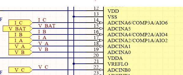
1) Can I map any of the analog current and voltage sense lines to any one of the analog pins on both A and/or B? I noticed that some of the designs divided the inputs between the A & B channels is this necessary for performance or is it arbitrary?
2) I would like to connect my current sense lines to pins that have both the ADC and the comparator function. I would like to use BOTH the ADC and the comparator at the same time. I would ike to use the ADC for the normal InstaSpinFOC functionality and the comparator for (unipolar) peak current fault detection. Is this possible?
Thanks,
Tim