This thread has been locked.

If you have a related question, please click the "Ask a related question" button in the top right corner. The newly created question will be automatically linked to this question.

TMS320F28377S: ISO1050 Problem with F28377S LaunchpadXL

Part Number: TMS320F28377S
Other Parts Discussed in Thread: ISO1050

Hello,

I'm having issues using can communication with the ISO1050 transciever and Launchpad XL.

The signal i see on the F28377S CANBRX pin is a 1Vpp communication signal ( attached is the image from the osciloscope with the waveform on the Rx pin from the tansciever ).
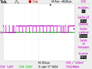
I'm using pins 33 and 34 from jumper J4 ( CANRXB and CANTXB) to communicate with the transciever. When i don't connect the transciever to the Launchpad, the waveform of the Rx pin is from 0V to 3.3V. When i connect the Tx and Rx from the ISO to the launchpad Pins, the signal drops to 1V .

Can this be a configuration issue ? Im using the typical CAN circuit ( 120R between CANL and CANH , 0,1uF Cap bypass near VCC1 and VCC2, VCC1 = 3.3V, VCC2 = 5V )

The CANB pin configuration i'm using is :

//CANB
GPIO_SetupPinMux(21, GPIO_MUX_CPU2CLA, 5); //CANRXB
GPIO_SetupPinOptions(21, GPIO_INPUT, GPIO_ASYNC);
GPIO_SetupPinMux(20, GPIO_MUX_CPU2CLA, 5); //CANTXB
GPIO_SetupPinOptions(20, GPIO_OUTPUT, GPIO_PUSHPULL);
EDIS;

Thanks.

Best Regards,

Bruno Duarte

  • Bruno,
    This is a single-core device. There is no CPU2 or CLA2. Can you please try GPIO_MUX_CPU1CLA?
  • Hello Hareesh,

    I've changed the config to :
    GPIO_SetupPinMux(21, GPIO_MUX_CPU1, 3); //CANRXB
    GPIO_SetupPinOptions(21, GPIO_INPUT, GPIO_ASYNC);
    GPIO_SetupPinMux(20, GPIO_MUX_CPU1, 3); //CANTXB
    GPIO_SetupPinOptions(20, GPIO_OUTPUT, GPIO_PUSHPULL);
    Is this configuration correct?

    Now the voltage on the RX pin stays on 3.3V.
    With the osciloscope i can see the comunication waveform on the CANH/CANL side but on the DSP side there is no signal.
    Am i Missing something ? Does the ISO1050 need any Pull Up or pull down aside from the 120ohm Termination resistor between CANL and CANH ?

    Another thing i've check is that when i dont have the RX from the ISO1050 connected to the RX from the F28377S, i have the waveform on the RX/TX side.

    Thank you

  • It appears the waveform at the RXD output of the transceiver is correct, as long as you don’t connect it to the MCU. Is this correct?


    I presume the ISO1050 is mounted on a different board. Is the GND of the MCU connected to GND1 of the ISO1050?


    ISO1050 datasheet mandates a pullup for the TXD pin, but not for the RXD pin. Are the pullups enabled inside the MCU?


    Can you provide the schematics for your setup?


    Sorry, I don’t understand what you mean by "Another thing i've check is that when i dont have the RX from the ISO1050 connected to the RX from the F28377S, i have the waveform on the RX/TX side". Please clarify.

  • Hareesh J said:

    It appears the waveform at the RXD output of the transceiver is correct, as long as you don’t connect it to the MCU. Is this correct?


    I presume the ISO1050 is mounted on a different board. Is the GND of the MCU connected to GND1 of the ISO1050?


    ISO1050 datasheet mandates a pullup for the TXD pin, but not for the RXD pin. Are the pullups enabled inside the MCU?


    Can you provide the schematics for your setup?


    Sorry, I don’t understand what you mean by "Another thing i've check is that when i dont have the RX from the ISO1050 connected to the RX from the F28377S, i have the waveform on the RX/TX side". Please clarify.

    Hello Hareesh,

    Yes, The waveform is on the RX pin of the transciever as long as i dont connect it to the MCU. Im connecting GND1 from the MCU to the transciever.

    Since i wasnt using the TX ( i was only interested in receiving data, not sending ) i didnt use the TX. I dont have any pull up there. Should i place ? 

    In the MCU i have the configuration o posted before.

    The last sentence was the same i told in the begging. If i connect the MCU, i dont have the waveform on the RX.

    Thanks.

  • How many nodes do you have on the network? If there are only two, then you must connect the CANTXB pin also to the transceiver, since this is needed to provide the ACK to the transmitting node. Yes, you need to add an external pullup, per ISO1050 datasheet.

    Please send schematics (wiring diagram) of your setup. Include a photograph as well.

  • Bruno,
    Please let us know if this issue has been resolved.
  • Hi Hareesh,

    We don't really know what the problem was. We swapped from CANA to CANB and eventually it worked. Probably it was not properly configured.

    I attached the configuration code that I have the CAN in case anyone else has the same problem.

    Thank you for the help.

    Best Regards

    	GPIO_SetupPinMux(21, GPIO_MUX_CPU1, 3); //CANRXB
        GPIO_SetupPinOptions(21, GPIO_INPUT, GPIO_ASYNC);
        GPIO_SetupPinMux(20, GPIO_MUX_CPU1, 3); //CANTXB
        GPIO_SetupPinOptions(20, GPIO_OUTPUT, GPIO_PUSHPULL);
    	EDIS;
    
    	// Initialize the CAN controllers
    //	CANInit(CANA_BASE);
    	CANInit(CANB_BASE);
    	// Setup CAN to be clocked off the PLL output clock
    //	CANClkSourceSelect(CANA_BASE, 0);   // 500kHz CAN-Clock
    	CANClkSourceSelect(CANB_BASE, 0);   // 500kHz CAN-Clock
    	// Set up the CAN bus bit rate to 500kHz for each module
    //	CANBitRateSet(CANA_BASE, 200000000, 500000);
    	CANBitRateSet(CANB_BASE, 200000000, 500000);
    	// Enable interrupts on the CAN
    //	CANIntEnable(CANA_BASE, CAN_INT_MASTER | CAN_INT_ERROR);// | CAN_INT_STATUS);
    	CANIntEnable(CANB_BASE, CAN_INT_MASTER | CAN_INT_ERROR);// | CAN_INT_STATUS);
    
    	DINT;
    	InitPieCtrl();
    	// Clear all interrupts and initialize PIE vector table:
    	IER = 0x0000;
    	IFR = 0x0000;
    	InitPieVectTable();
        EALLOW;  // This is needed to write to EALLOW protected registers
        PieVectTable.TIMER0_INT = &cpu_timer0_isr;
        PieVectTable.SCIA_RX_INT = &sciaRxFifoIsr;
        PieVectTable.SCIB_RX_INT = &scibRxFifoIsr;
    //    PieVectTable.CANA0_INT = canaISR;
        PieVectTable.CANB0_INT = canaISR;
        PieVectTable.ADCA1_INT = &adca1_isr;
        EDIS;    // This is needed to disable write to EALLOW protected registers
    
        //INICIALIZAÇAO TIMER 0
        InitCpuTimers();   // For this example, only initialize the Cpu Timers
    	ConfigCpuTimer(&CpuTimer0, 200, 20);	//Iniciacializa o timer para a amostragem dos ADC (10000HZ)
    
        scia_config();
        scib_config();
    
    	IER |= 0x101; // Enable CPU INT
    	// Enable interrupts required for this example
    	PieCtrlRegs.PIECTRL.bit.ENPIE = 1;   	// Enable the PIE block
    	PieCtrlRegs.PIEIER1.bit.INTx7 = 1;		//PIE group 1, timer0
    	PieCtrlRegs.PIEIER9.bit.INTx1 = 1;     	// PIE Group 9, INT1 SCIA_RX interrupt
    	PieCtrlRegs.PIEIER9.bit.INTx3 = 1;		// PIE Group 9, INT1 SCIB_RX interrupt
    	PieCtrlRegs.PIEIER9.bit.INTx5 = 1;		//CAN Interrput ?
    	PieCtrlRegs.PIEIER9.bit.INTx7 = 1;		//CAN Interrput CANB_0
    	PieCtrlRegs.PIEIER1.bit.INTx1 = 1; 		// Enable interrupt ADC
    	EINT;
    	ERTM;
    
    	// Enable the CAN-A interrupt signal
    //	CANGlobalIntEnable(CANA_BASE, CAN_GLB_INT_CANINT0);
    	CANGlobalIntEnable(CANB_BASE, CAN_GLB_INT_CANINT0);
    
        EALLOW;
        CpuSysRegs.PCLKCR0.bit.TBCLKSYNC = 0;
        EDIS;
    
        InitEPwm2();
    
        EALLOW;
        CpuSysRegs.PCLKCR0.bit.TBCLKSYNC = 1;
        EDIS;
    
        //Configuração da MailBox
    	sRXCANMessage1.ui32MsgID = 0x100;
        sRXCANMessage1.ui32MsgIDMask = 0x7ff; // accept 0x400;
        sRXCANMessage1.ui32Flags = MSG_OBJ_RX_INT_ENABLE | MSG_OBJ_USE_ID_FILTER ;
        sRXCANMessage1.ui32MsgLen = MSG_DATA_LENGTH;
        sRXCANMessage1.pucMsgData = rxMsgData1;
    //    CANMessageSet(CANA_BASE, 1, &sRXCANMessage1, MSG_OBJ_TYPE_RX); // configure the first adress for the 0x10;
        CANMessageSet(CANB_BASE, 1, &sRXCANMessage1, MSG_OBJ_TYPE_RX); // configure the first adress for the 0x10;
    
        //Configuração da MailBox
    	sRXCANMessage2.ui32MsgID = 0x102;
        sRXCANMessage2.ui32MsgIDMask = 0x7ff; // accept 0x400;
        sRXCANMessage2.ui32Flags = MSG_OBJ_RX_INT_ENABLE | MSG_OBJ_USE_ID_FILTER ;
        sRXCANMessage2.ui32MsgLen = MSG_DATA_LENGTH;
        sRXCANMessage2.pucMsgData = rxMsgData2;
    //    CANMessageSet(CANA_BASE, 2, &sRXCANMessage2, MSG_OBJ_TYPE_RX); // configure the first adress for the 0x10;
        CANMessageSet(CANB_BASE, 2, &sRXCANMessage2, MSG_OBJ_TYPE_RX); // configure the first adress for the 0x10;
    
        //Config ADC
        AdcConfig();
        // Start CAN module A
    //    CANEnable(CANA_BASE);
        CANEnable(CANB_BASE);
        //start Timer
        CpuTimer0Regs.TCR.all = 0x4001;