Part Number: LAUNCHXL-F28377S
Hi all
I would like to establish the communication between PC computer and LaunchPad F28377S. I spend a lot of time to do it.
There are the hardware facts:
1) On the board is located the dedicated gold pins for CAN connection. This pins are (CAN-L, CAN-H and GND). Further there is the Bus Transceivers (SN65HVD234D). The output of this device are D (CAN Transmit data TXD ) and R (CAN Recive data RXD ). Via resistors R43 and R44 are connected into processors pins: 76 (GPIO70 -- CANRxA) and 76 (GPIO 71-- CANTxA)
There are the software facts:
1) I analyzed examples from ControlSuit for device type F2837xS.
C:\ti\controlSUITE\device_support\F2837xS\v210\F2837xS_examples_Cpu1.
2) I wrote the documentation F2837xS-DRL-UG.pdf
3) Based on these information I develop the software for CAN as bellow (only CAN transmission functionality).
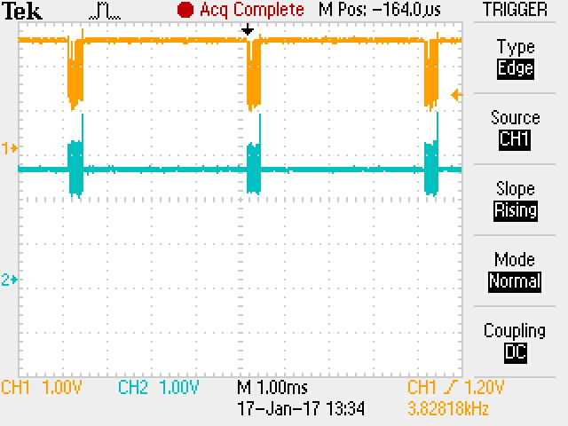
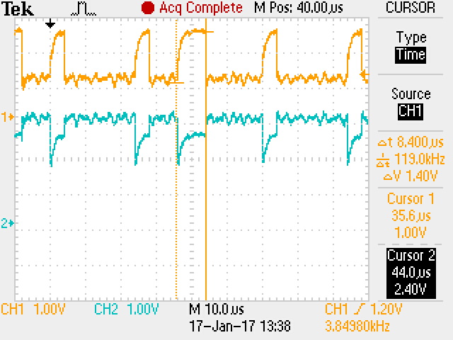
I can not observe any information on CAN-L and CAN-H. Using scope I see only value for both signals around 2,5V.
So I am asking to help me with this problem. Please point me where I am wrong in my thinking and which way I have to go.
I will be waiting for your response.
Best regarst
//###########################################################################
#include "F28x_Project.h" // Device Headerfile and Examples Include File
#include <stdint.h>
#include <stdbool.h>
#include "inc/hw_types.h"
#include "inc/hw_memmap.h"
#include "inc/hw_can.h"
#include "driverlib/can.h"
unsigned char txMsgData[4];
tCANMsgObject sTXCANMessage;
void main(void)
{
InitSysCtrl();
InitGpio();
GPIO_SetupPinMux(70, GPIO_MUX_CPU1, 1); //GPIO70 - CANRXA
GPIO_SetupPinOptions(70, GPIO_INPUT, GPIO_ASYNC);
GPIO_SetupPinMux(71, GPIO_MUX_CPU1, 1); //GPIO71 - CANTXA
GPIO_SetupPinOptions(71, GPIO_OUTPUT, GPIO_PUSHPULL);
CANInit(CANA_BASE);
//
//CANBitTimingSet(address of CAN, points to the structure with the clock parameters (pClkParams))
//
//
// Setup CAN source clock. Select option
// CANClkSourceSelect(base address of CAN, clock source) 0 - Selected CPU SYSCLKOUT
CANClkSourceSelect(CANA_BASE, 0);
//
// CANBitRateSet(base address of CAN, clock freq for CAN in Hz, bit rate)
CANBitRateSet(CANA_BASE, 200000000, 250000);
DINT;
InitPieCtrl();
IER = 0x0000;
IFR = 0x0000;
// pMsgObject
sTXCANMessage.ui32MsgID = 0x203; // either 11 or 29
//sTXCANMessage.ui32MsgIDMask = 0;//0x7F8; // NONE;
sTXCANMessage.ui32Flags = MSG_OBJ_TX_INT_ENABLE;
//sTXCANMessage.ui32Flags = 0;
sTXCANMessage.ui32MsgLen = 4;
sTXCANMessage.pucMsgData = txMsgData;
txMsgData[0] = 0x12;
txMsgData[1] = 0x34;
txMsgData[2] = 0x56;
txMsgData[3] = 0x78;
CANEnable(CANA_BASE);
for(;;)
{
txMsgData[0] = 0x12;
txMsgData[1] = 0x34;
txMsgData[2] = 0x56;
txMsgData[3] = 0x78;
//
// Transmit Message
//CANA_BASE base address of CANA
//ObjID---object number to configuration 1-32 (Mail boxes)
//pMsgObject-----pointer to a structure containing massage object settings,
//eMsgType-------indicate the type of message for object);
//
CANMessageSet(CANA_BASE,2, &sTXCANMessage,MSG_OBJ_TYPE_TX);
DELAY_US(1000 * 250);
}
}