This thread has been locked.

If you have a related question, please click the "Ask a related question" button in the top right corner. The newly created question will be automatically linked to this question.

TMS320F28377D: Cannot realize CAN external loopback mode operation with example code

Part Number: TMS320F28377D
Other Parts Discussed in Thread: SN65HVD235

Hi,

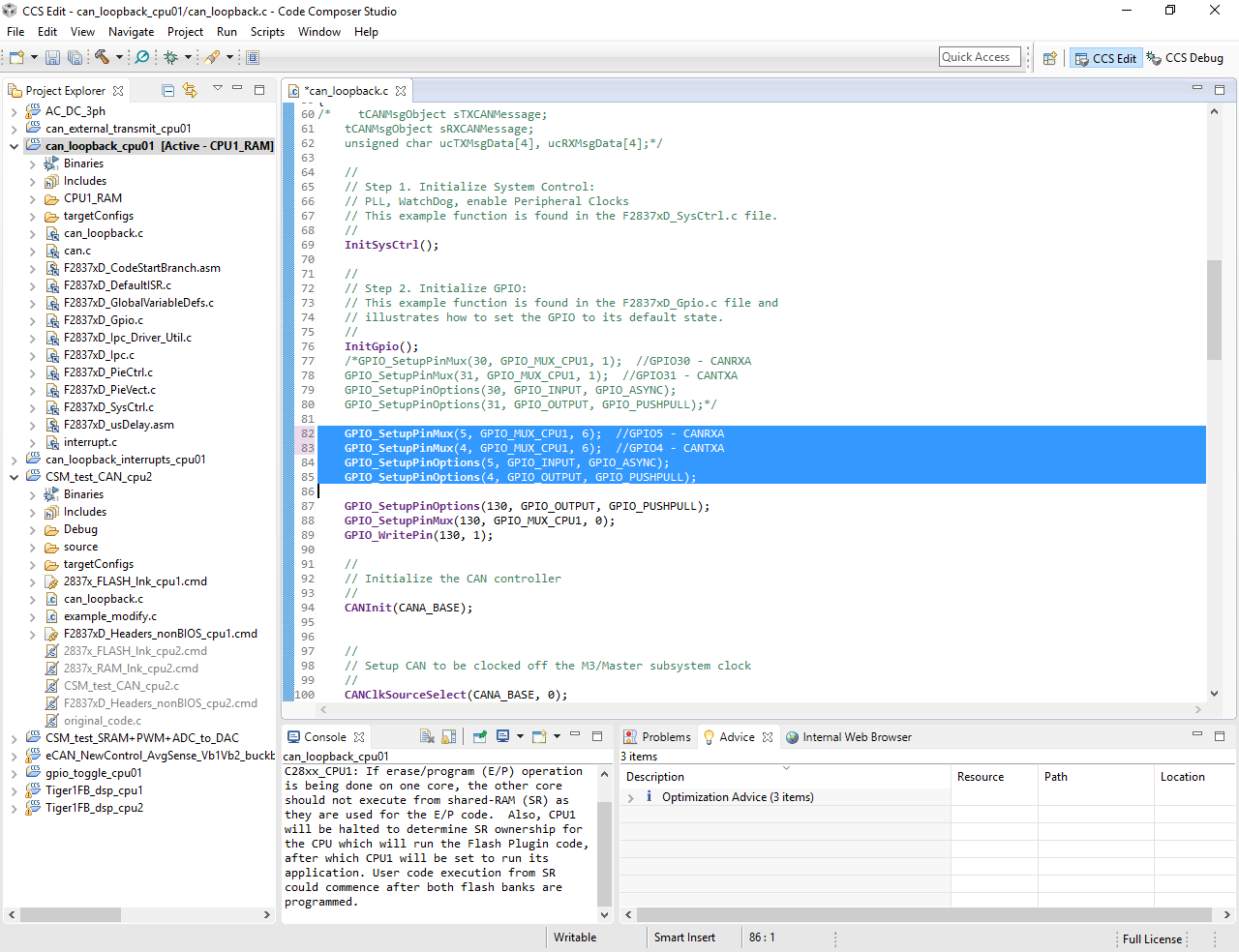
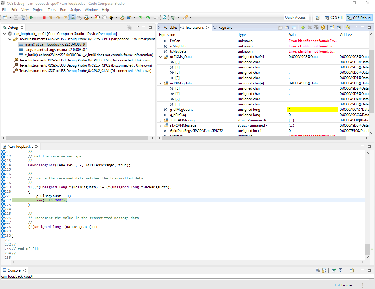
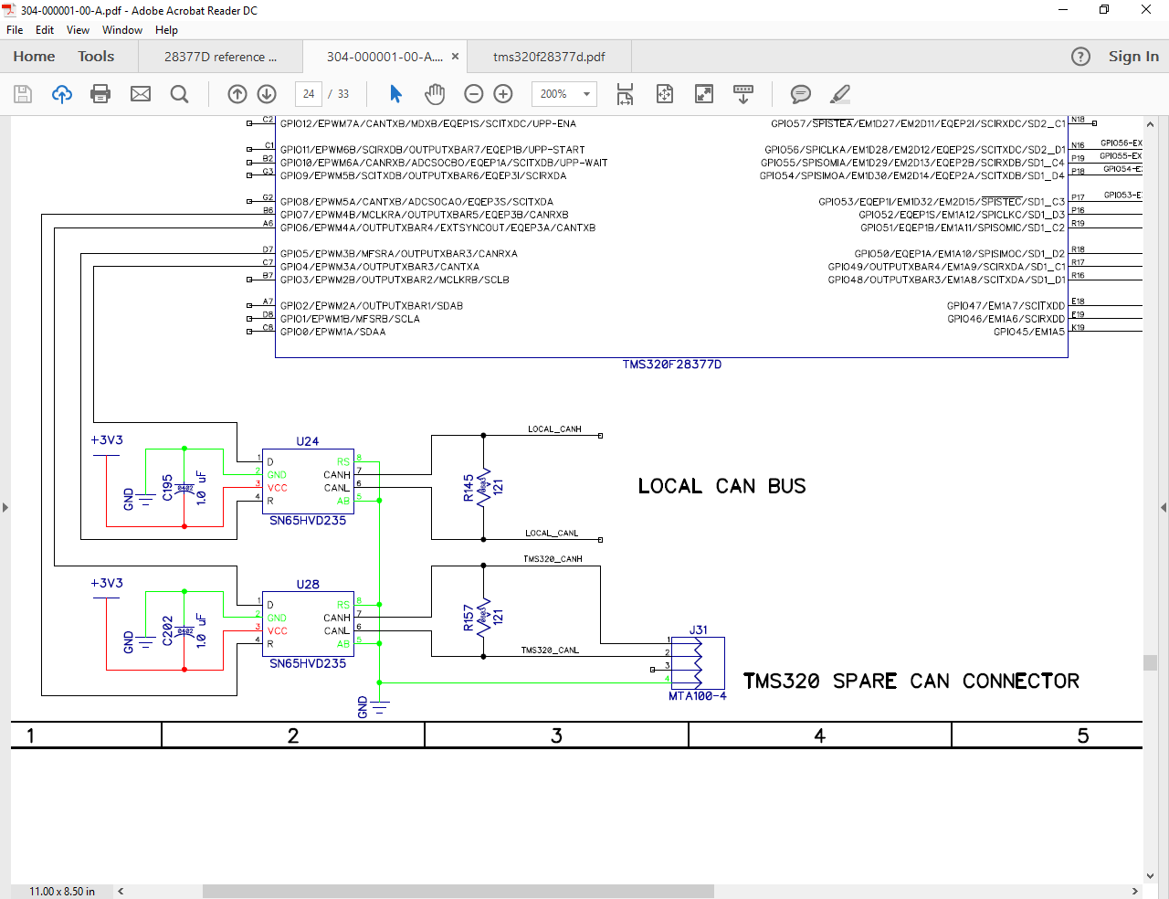
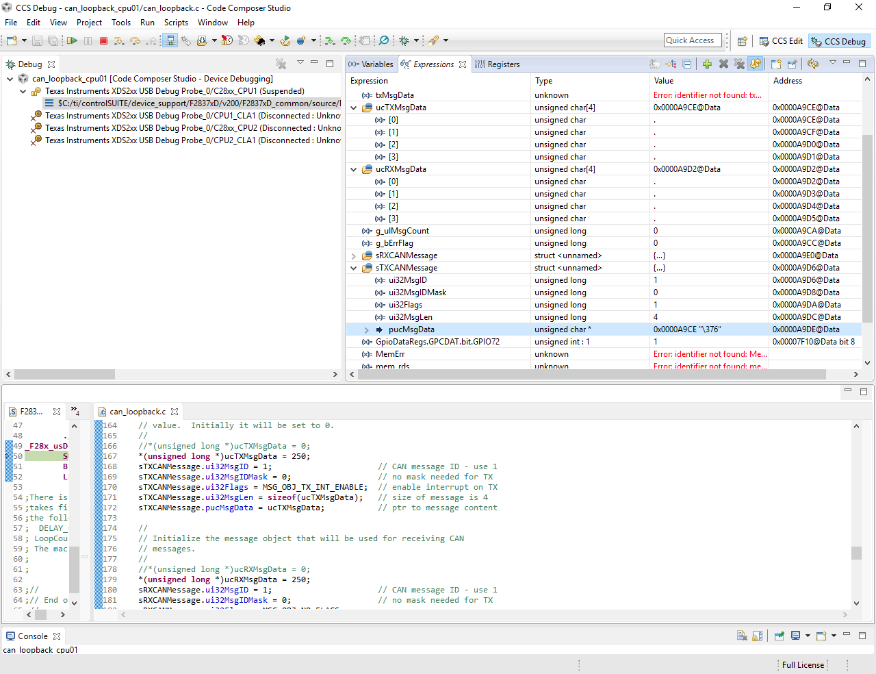
I tried to start CAN communication from external loopback example. What I did is just modifying GPIO pin which we use (GPIO 5/4), and everything else is kept unchanged. But when I debugged it, I cannot even observe value written in array for transmitting (0 in example), which shows as below. And then the program stops because of the mismatch. The program and debugging view is shown below, also attached schematic for CAN connection. I programmed CAN for 28032 before, but 28377d provides less direct view on things, which makes me very confused. Can anyone give hints on what happens? Thanks a lot.

  • Yi,

                Merely changing the GPIO assignments should not affect the way the example works. Questions:


    1. Were you able to see the data in the array when you ran the example "as is"? (i.e. with the original GPIO assignments)
    2. Are you trying to run this code in self-test (loopback) mode or are you trying to communicate with another node?
    3. What hardware platform are you using?

  • Hi Hareesh,

    Thanks for the timely reply.
    1.
    I go back to original example code and simply change
    *(unsigned long *)ucRXMsgData = 0;
    to
    *(unsigned long *)ucRXMsgData = 48;
    Now I can observe value as "0". I think it is because of char corresponding to ASCII code that I cannot see anything meaningful before. And it seems running self-test already, although the pin assignment is "wrong". Does it mean that I do not need to connect CAN pins to transceiver for self-test and any GPIO(CAN) pins can be assigned to operate in self-test mode?
    2.
    I tried to run this code in loopback mode first to demonstrate its functionality and deepen my understanding. Then I need to communicate with another node
    3.
    I use SN65HVD235 as transceiver and try to communicate with imx6 at last.

    It seems example code works and I can go on to modify it. One more question: I want to run CAN communication at cpu2, in which case I need to assign GPIO pins to cpu2 and CAN selection to cpu2 as following. Is there anything else to configure running in cpu2?
    GPIO_SetupPinMux(4, GPIO_MUX_CPU2, 6);
    EALLOW;
    DevCfgRegs.CPUSEL8.bit.CAN_A = 1;
    DevCfgRegs.CPUSEL8.bit.CAN_B = 1;
    EDIS;

    Best,
    Yi
  • Hi Hareesh,

    I ran the example code for several times and found another issue. Although it can run successfully for the first hundreds of loops, it will stop at around "\377". As

    *(unsigned long *)ucRXMsgData = 48;

    shows, it is "long" type now and should be more than that. And as

    unsigned char ucTXMsgData[4]

    shows, if the value increases up to 255, it should be automatically load to ucTXMsgData[1] from ucTXMsgData[0], right? In this case I can observe number or symbol (corresponds to ASCII) as in ucTXMsgData[0], but nothing happens. I wonder what the limit should be. I am very confused since there are lots of forced type conversions, can you give some hints?

    The first picture is normal function, and the second is what happens a second before error occurs. (g_ulMsgCount = 1 indicates error)

  • Yi zhang said:
    Hi Hareesh,

    Thanks for the timely reply.
    1.
    I go back to original example code and simply change
    *(unsigned long *)ucRXMsgData = 0;
    to
    *(unsigned long *)ucRXMsgData = 48;
    Now I can observe value as "0". I think it is because of char corresponding to ASCII code that I cannot see anything meaningful before. And it seems running self-test already, although the pin assignment is "wrong". Does it mean that I do not need to connect CAN pins to transceiver for self-test and any GPIO(CAN) pins can be assigned to operate in self-test mode?

    Answer: That is correct.


    2.
    I tried to run this code in loopback mode first to demonstrate its functionality and deepen my understanding. Then I need to communicate with another node
    3.
    I use SN65HVD235 as transceiver and try to communicate with imx6 at last.

    It seems example code works and I can go on to modify it. One more question: I want to run CAN communication at cpu2, in which case I need to assign GPIO pins to cpu2 and CAN selection to cpu2 as following. Is there anything else to configure running in cpu2?
    GPIO_SetupPinMux(4, GPIO_MUX_CPU2, 6);
    EALLOW;
    DevCfgRegs.CPUSEL8.bit.CAN_A = 1;
    DevCfgRegs.CPUSEL8.bit.CAN_B = 1;
    EDIS;
    Answer:  You need to do this for all concerned GPIO pins.


    Best,
    Yi

  • Yi zhang said:

    Hi Hareesh,

    I ran the example code for several times and found another issue. Although it can run successfully for the first hundreds of loops, it will stop at around "\377". As

    *(unsigned long *)ucRXMsgData = 48;

    shows, it is "long" type now and should be more than that. And as

    unsigned char ucTXMsgData[4]

    shows, if the value increases up to 255, it should be automatically load to ucTXMsgData[1] from ucTXMsgData[0], right? In this case I can observe number or symbol (corresponds to ASCII) as in ucTXMsgData[0], but nothing happens. I wonder what the limit should be. I am very confused since there are lots of forced type conversions, can you give some hints?

    The first picture is normal function, and the second is what happens a second before error occurs. (g_ulMsgCount = 1 indicates error)

    Hello,

    In the register view, you can right-click on the TX and RX data arrays, and change the display format to HEX to better see the contents of the array.

    The error (of which the TX and RX data don't match), always occurs at the same point?

    Best Regards

    Chris

  • Hi Chris,

    I think "\377" corresponds to "255" in decimal and the error still happens even if I give value to individual array member instead of the whole array. And it seems the "\377" error always occurs at highest member of array.

    Because when I program like this:

    txMsgData[0] = 0x12;
    txMsgData[1] = 0x12;
    txMsgData[2] = 0x12;
    txMsgData[3] = 0xEE;
    txMsgData[4] = 0xE0;

    Then increase each member by 1 during each for loop. The error only occurs when txMsgData[4] increase to "\377".

    But if I program like this:

    txMsgData[0] = 0x12;
    txMsgData[1] = 0x12;
    txMsgData[2] = 0x12;
    txMsgData[3] = 0xE0;

    The error only occurs when txMsgData[3] increase to "\377".

    I am confused how this happens only to highest byte. And after I use "if" to identify "\377" point and clear it to zero at that point, there is no error.

    Can you give any hints on that? Since they are written in individual byte, there should not be conflict even if one byte exceeds its limit.

    Thanks,

    Yi

  • Yi,

    I did some testing and I'm not seeing a data match error. I do think this example needs to be fixed to increment data for each array index individually. Additionally, I'm filing a bug to have a checked added, so that whenever any of the indexes exceed 0xFF, they will be reset to zero. When data is incremented past 0xFF, it rolls to 0x100 which then transmits zeros (driver API only takes the lower byte).

    Best Regards
    Chris
  • Hi Chris,

    Thanks for getting back to me. And I modified the code similarly and it turned out to be fine.At least there is no error now. But as I mentioned in the last post, even if the other indexes increase to 0xFF earlier, there is no error and they will go back to 0 then start again. But things are different for the highest index, which shows error when it increases to 0xFF. That is what I am still confused and curious now. If there is no quick answer right now, I can totally understand. Thanks a lot anyway.

    Yi