This thread has been locked.

If you have a related question, please click the "Ask a related question" button in the top right corner. The newly created question will be automatically linked to this question.

CCS/TMDSHV1PHINVKIT: TMDSHV1PHINVKIT Output wave form is square shape, not SINE

Part Number: TMDSHV1PHINVKIT

Tool/software: Code Composer Studio

Hi

I am checking this kit. 

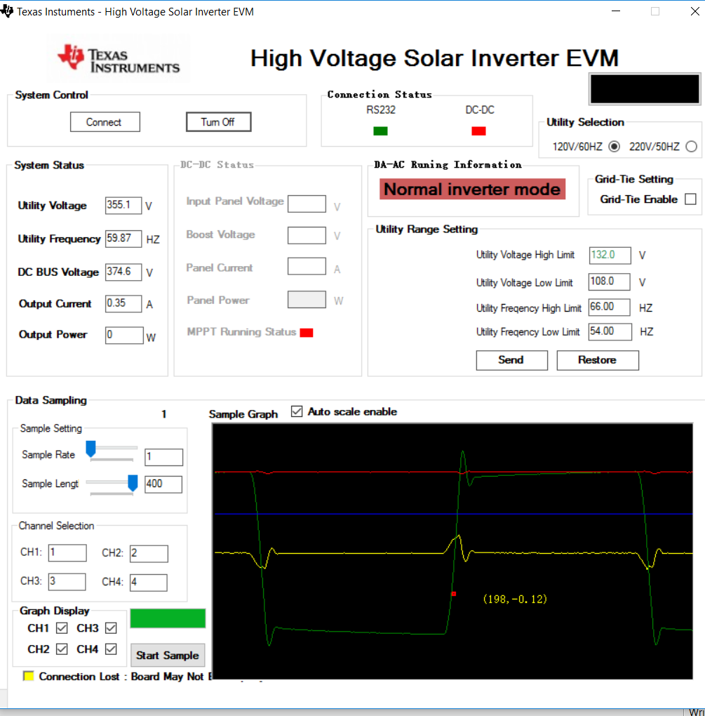
I get output wave form as square shape, not sine wave.

I have attached it.

also even I can't get 50Hz by changing from given GUI. Please help me.

check attached image.

My controller card is Concerto 28x.

Here is my Solar DC_AC_settings.h file.

#ifndef _PROJSETTINGS_H
#define _PROJSETTINGS_H

//**********************************************************************************
//  NOTE: WHEN CHANGING THIS FILE PLEASE REBUILD ALL
//**********************************************************************************

//==================================================================================
// Incremental Build options for System check-out
//==================================================================================
// BUILD 1 	Open loop boost check + ADC feedback
// BUILD 2 	Complete PFC Build
 
#define INCR_BUILD 3
#define VoltCurrLoopExecRatio	8
#define Protect_Enable	1
#define	Protect_Utiligy_Enable  1
		

//==================================================================================
// Interrupt Framework options
//==================================================================================

#define EPWMn_DPL_ISR	0	// for EPWM triggered ISR set as 1
#define ADC_DPL_ISR	    1	// for ADC triggered ISR set as 1

//----------------------------------------------------------------------------------
// If EPWMn_DPL__ISR = 1, then choose which module
//----------------------------------------------------------------------------------
/*
#define EPWM1			1	// EPWM1 provides ISR trigger
#define EPWM2			0 	// EPWM2 provides ISR trigger
#define EPWM3			0	// EPWM3 provides ISR trigger
#define EPWM4			0	// EPWM4 provides ISR trigger
#define EPWM5			0	// EPWM5 provides ISR trigger
#define EPWM6			0	// EPWM6 provides ISR trigger
*/
//==================================================================================
// System Settings
//----------------------------------------------------------------------------------
#define HistorySize 8


#endif //_PROJSETTINGS_H

Please help me as soon as possible.

Thank you

  • Hi,

    Did you follow the Quick starter's guide from here:
    C:\ti\controlSUITE\development_kits\HV_SOLAR_DC_AC_v1.1\~Docs

    Regards,
    Gautam
  • yes, I am following.
    My load was small 5W LED bulb that runs from 230V. is that effect?
    also I could not tell you, my broad was damaged and repaired. I did open loop test, I get square shape output.

    could you please help?
  • Athula Kumara said:
    also I could not tell you, my broad was damaged and repaired. I did open loop test, I get square shape output.

    Did you check the output on a DSO? Is it square wave there too?

  • DSO?
    do you mean the gate signals?
    I will check each gate signals tomorrow and let you know.
    Thank you!
  • yes, I checked output from DSO.
    with ISOlation probes.
    I checked AC line using it, and it shows nice sine wave. but inverter output is square.

    I removed two drivers and tried to run system using only two IGBT, which are not in same column or row.

    What i observe is only positive DC at output
  • It seems like there are more damaged parts. What you can do is check the outputs on the board stage-by-stage. Let me link you to to help you narrow down the damaged part.

    Regards,
    Gautam
  • Hi
    I reloaded the program after done few modifications.
    Finally now I am getting full sine wave! That's done.

    Now I need to change frequency to 50Hz, I can't do it using GUI.
    Where I have to edit in the code to achieve this?

    Please help me.
  • I don't need 60Hz, I only need to have 50Hz, but my system default is 60Hz/120V. I want to make it to only 50Hz.
    I can now switch to 50Hz using GUI, But I hope to use this with 50Hz systems, so I need to have default system of 50Hz, otherwise inverter will burn when it try to connect to 50Hz system while it producing 60Hz/120V output.

    My programming knowledge is not good. but I can manage to do some works, if you need I can attach the code.
    or you can have it in this address.
    ti\controlSUITE\development_kits\HV_SOLAR_DC_AC_v1.1\Solar_HV_DCAC_Concerto_SCI_Rev_0\c28

    Thank you!
  • Please update me
  • Please see figure 3.3.2 in the UG,

    you will see GEN_SIN_COS is the routine that provides the angle in case when grid is not connected,

    hence you need to change this variable..

    search for the below in the code..

    GEN_SIN_COS_Ws = &dwPll_Trace_Freq;

    and change the variable accordingly.
  • Hi
    I figured out it should be the variable. but I don't understand what is IQ20 format is. there they have used IQ20 format and for 60Hz they have used some value.
    I do not know how to calculate it for 50Hz.
    I could not find a way to calculate it in INTERNET.
    please help me if you know it.
    I found that is is Ti math libary thing. but I am very new to CCS so I do not know it.

    Thanks