This thread has been locked.

If you have a related question, please click the "Ask a related question" button in the top right corner. The newly created question will be automatically linked to this question.

TMS320F28377D: 16-bit differential analog input

Part Number: TMS320F28377D

Hi,

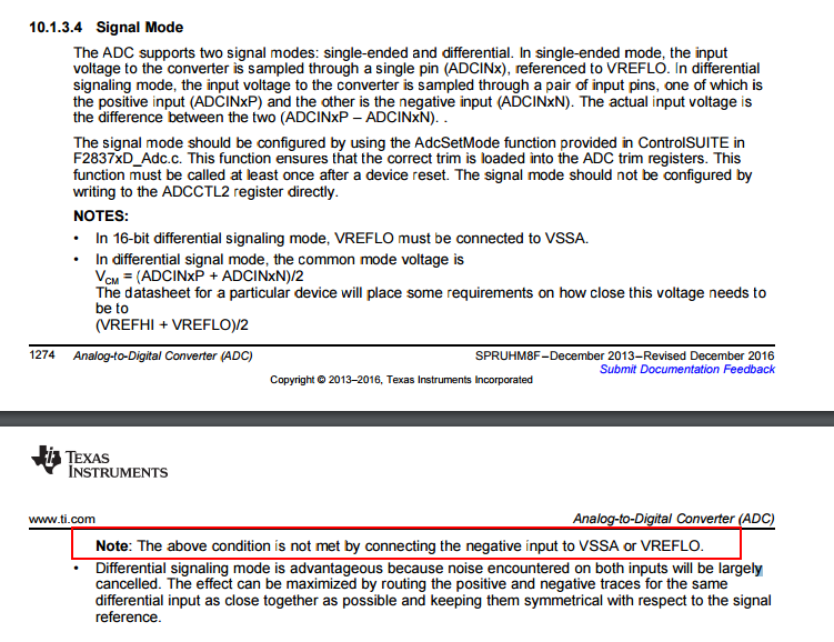
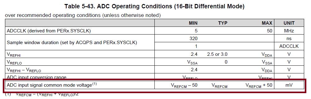
I want to use 16-bit ADC resolution for my application. I have configured my ADC module in 16-bit differential configuration. Currently i am applying 0V to 3.3V on ADCINxP and keeping 0V on ADCINxN.

Is this configuration has any disadvantage??

Regards,

Maulik Timbadiya 

  • Hi Maulik,

    This is applying a single-ended input to a differential ADC.  The ADC will not function correctly.  We give guidance on this in the TRM (spruhm8f):

  • Thanks Devin Cottier,

    I want to use 16-bit differential ADC. Please suggest circuitry?? I am really confused about that.

    As you know differential signal are potentially opposite in nature, and you are saying that if i apply 3.3V to ADCINxP and 0V to ADCINxN then it will not work?? then how can i make it work??

    And please guide me for red marked area, What TI wants to say??

    Regards,

    Maulik Timbadiya

  • Hi Maulik,

    The two differential inputs should be complimentary about the common mode voltage. As you have highlighted in the table above, the common mode voltage should be close to (VREFHI - VREFLO) / 2.  For example then if VREFHI is 3.0V then the common mode voltage should be close to 1.5V.

    If the common mode voltage is 1.5V and the ADC reference range is 0 to 3.0V then the maximum possible input is Vin+ = 3.0V and Vin- = 0V and the lowest possible input is Vin+ = 0V and Vin- = 3.0V.  The negative input must move to maintain a constant common mode voltage, so if Vin+ = 2.1V then Vin- should be 0.9V.  This is why you can't just tie the negative input to ground.  

    The specification you have highlighted above specifies how far off the common mode voltage can be from ideal while allowing the ADC to still function.  If the signal is ideally Vin+ = 1.1V and Vin- = 1.9V, then the DC level of both inputs can drift up or down by up to 50mV.  +50mV would give Vin+ = 1.15V and Vin- = 1.95V and -50mV would give Vin+ = 1.05V and Vin- = 1.85V.  All 3 of these input voltage conditions should give the same ADC output code because the difference between the positive and negative inputs is the same. 

    To supply a differential voltage to the ADC, you can either sample a sensor that is already in a differential format, or you can convert a single-ended signal to differential by using either a fully-differential op-amp (e.g. THS4531) or you can use a pair of single-ended op-amps.  The precision amplifier e2e forum can help with designing appropriate signal conditioning circuitry if necessary.  

  • Thanks Devin Cottier,

    The way you answered my question is pretty good. 

    Now, my question is related to ADC count conversion. Suppose, i have made a circuit that is maintain common mode voltage to 1.65 (VREFHI = 3.3V and VREFLO 0V). I am applying +2.2V to Vin+ and circuit will generate +1.1V on Vin- to maintain constant common mode voltage.

    Now, The expected ADC count is 54613 (2.2V and 0V) in software but by maintaining common mode voltage i am getting 43690 (2.2V and 1.1V). So Is there any standard formula to convert my differential format result into single ended format result? Simply how can i convert 43690(Vin+ = 2.2 and Vin- = 1.1) to 54613(Vin+ = 2.2 and Vin- = 0)?

    Thanks and Regards,

    Maulik Timbadiya

  • Hi Maulik, 

    See "10.1.3.5 Expected Conversion Results" in the TRM (link below)

    Digital Result = 65536*(In_p - In_n + VREFHI)/(2*VREFHI) = 65536*(2.2 - 1.1 + 3.3) / 6.6 = 43691

    http://www.ti.com/lit/ug/spruhm8f/spruhm8f.pdf