This thread has been locked.

If you have a related question, please click the "Ask a related question" button in the top right corner. The newly created question will be automatically linked to this question.

TMS320F28069F: Doubt about EQEP based control

Part Number: TMS320F28069F

Hello

I want to run a sensored torque control using an encoder. 

I have adapted Lab4a in order to do that:

I have initiated the encoder handles etc

and I also have passed the encoder's read to the control in mainISR function

CTRL_run(ctrlHandle,halHandle,&gAdcData,&ENC_getElecAngle(encHandle));

I have perform all the steps gives in the spruhf1 except this one (QEPctrl.h)

angle_pu = EST_getAngle_pu(obj->estHandle);
// Update electrical angle from ENC module
angle_pu = ENC_getElecAngle(encHandle);

I have not modified this because in Lab12 labs these lines are not included

Is this correct?

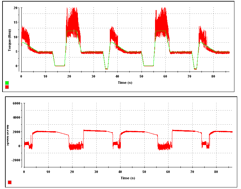
The control works correctly but it seems to have more torque Ripple that the one without encoder (Lab4a). Encoder resolution is 512 (I think it should be enough)

Is there any missed?

I have read in previous post that speed feedback is not provided by the encoder firmware. Is it true?

I have another question

Due to my application (Powertrain with in wheel motors) encoder aligment phase is no desirable for real application. We have included a dual incremental and absolute encoder. Is there any example about the way to perform the offset initialization. I have performes some multiples encoder aligment process (during Rs recalculation step) and depending on the motor initial position (previous to Rs recalibration step) we have obtained four position: 1591, 1079, 567, 55 (the motor has 4 pole pairs, and we use a 2048 abs encdder). Depending the test these positions have a desviation of +/-50. My idea is to used this pre-calculated position to set the offset. Is this desviation critical to do that? Is there example about the way in which these points can be transformed into a valid offset

Thank you in advace

Borja Gómez

  • Borja,

    Borja Gomez88 said:
    // Update electrical angle from ENC module
    angle_pu = ENC_getElecAngle(encHandle);

    This step is required, else the FOC will use the estimator as its angle source and not the encoder.  

    Borja Gomez88 said:
    I have read in previous post that speed feedback is not provided by the encoder firmware. Is it true?

    The ENC software module doesn't calculate the speed by default, however there are functions to enable this provided.

    Borja Gomez88 said:
    Is there any example about the way to perform the offset initialization.

    Due to the wide variety of encoders available, there isn't an example provided.  You should be able to use your experimental information and encoder to create an offset that isn't dependent on the initial rotor position.  The ENC module is trying to convert the mechanical position into an electrical position and in order to do that it needs to wrap the angle from 0 to 1 for each electrical angle.  So you should be able to modify the code so that your offset is not taken from the mechanical reading but from the electrical reading instead.

  • Dear Mr Reynolds

    Thank you for your reply.

    This step is required, else the FOC will use the estimator as its angle source and not the encoder. 

    I was wrong. I did not realized the I was using the "ENC_getElecAngle(encHandle)". In CTRL_runOnLine_User fucntion the electricalAngle is an input argument (and is obtained from Encoder reads in main_ISR function

    // generate the motor electrical angle
    angle_pu = EST_getAngle_pu(obj->estHandle);

    // Update electrical angle from the sensor
    angle_pu = electricalAngle;

    Due to the wide variety of encoders available, there isn't an example provided.  You should be able to use your experimental information and encoder to create an offset that isn't dependent on the initial rotor position.  The ENC module is trying to convert the mechanical position into an electrical position and in order to do that it needs to wrap the angle from 0 to 1 for each electrical angle.  So you should be able to modify the code so that your offset is not taken from the mechanical reading but from the electrical reading instead.

    Using the SSI encoder I have managed to program a alignment function. Depending of the rotor position the Rs recalibration process moves the rotor to a four fixed positions (SSI position). This info can be used to initialize the offset without the use of the "Rs recalibration process"

    So at this point I though that both HW and SW were correct, but there are not. I have some problems when high torques are demanded (3*Rated Torque. > 80% ADC Scale for current measurement). For test purposes I'm running an standard driving cycle. Torque reference is sent to the control via CAN and the same bus is used to get the speed and torque. In the following graphs torque reference (green), torque measured (red) and motor speed are shown. If "Torque graph" is analized it can be seen that during some periods (high torques (3*Tn)) the torque ripple is quite high. During this periods speed info (from estimator) is not correct. It oscilates around zero.

    The motor is coupled to another motor that acts as a load (load depends on the road, vehicle params, grade, ...). A torque sensor has been disposed between both motor. If we take info from this sensor and the load motor we can see that the generated torque is tracking the commanded torque (avg info) and that the real speed is also correct. What can cause this divergency between real and measured speeds and torques? It could be a noise problem? 

    Thank you in advance

    Borja

  • Hi Borja,

    Which graph tool did you use to display the Torque and Speed?

    Thank for sharing in advance,
  • Hi!

    I'm using ControlDesk from DSpace

    www.dspace.com/.../controldesk.cfm

    I'm just reading CAN messages from a custom board

    Best regards