This thread has been locked.

If you have a related question, please click the "Ask a related question" button in the top right corner. The newly created question will be automatically linked to this question.

LAUNCHXL-F28377S: Problem with usb_dev_bulk example on the F28377S

Part Number: LAUNCHXL-F28377S

Hello!

I am trying to get the usb_dev_bulk-example with the LaunchpadXL-F28377S to work on Windows 10 x64. I should also note that  I am using a modified cable where D+,D- and GND are directly connected to Pin 9 (GPIO43), Pin 10 (GPIO42) and GND.

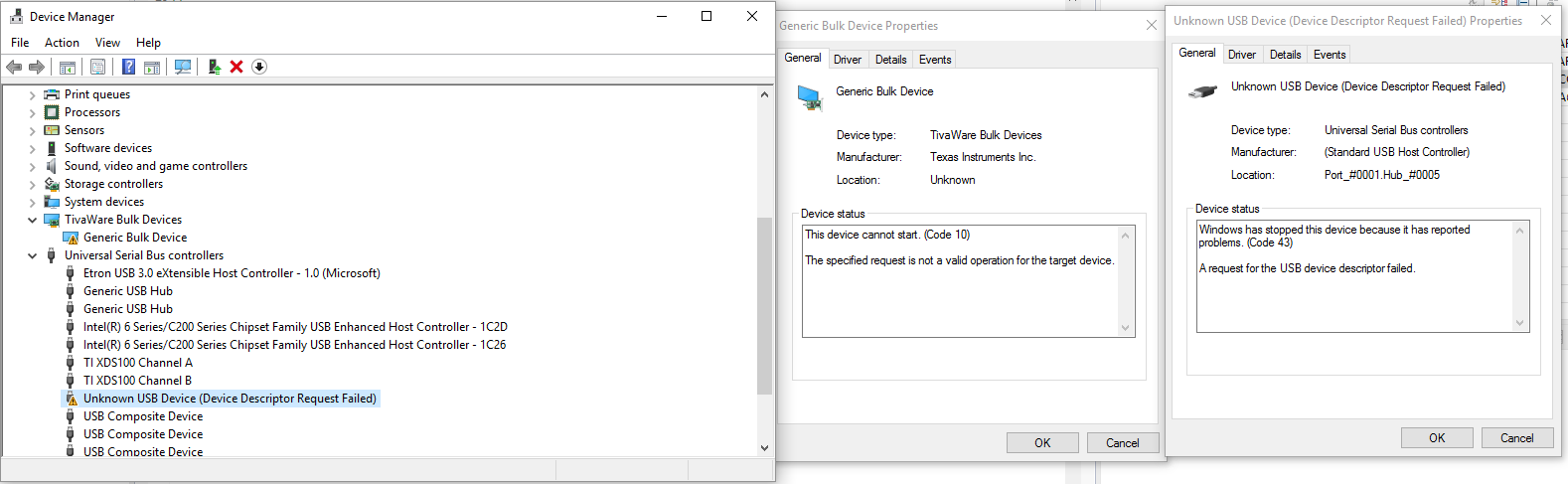
So far I can get Windows to recognize that something has been plugged in but it gets only identified as "Unknown USB Device (Device Descriptor Request Failed". While looking through this forum I have encountered various other threads about the same issue but with different devices. Most issues seem to boil down to driver related stuff. Here is a list of things that i have tried until now:

  • Turn off driver signature enforcement

  • device in device manager -> update driver -> pick folder "...\device_support\F2837xS\v210\F2837xS_common\windows_drivers". Result: Windows says that the best driver is already isntalled.

  • update driver and specifically pick usb_dev_bulk.inf. Result:

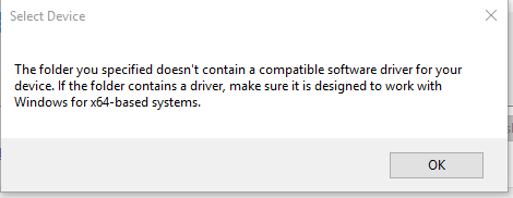
  • press windows+R, open open hdwwiz and open usb_dev_bulk.inf. Result: It is now possible to install the driver and after that it appears in the Device Manager but its still not working.

  • I have also tried the things above with the TivaWare 2.1.3 driver package from ti.com/tool/SW-TM4C

  • Accodring to this thread (e2e.ti.com/support/microcontrollers/c2000/f/171/t/554848) there is a bug in the v210 version of the dual core variant of my chip. However even after applying the suggested fix and also trying v200, v190 and v160 it still does not work

  • I can set a breakpoint rigth at the start of uint32_t RxHandler(void *pvCBData, uint32_t ui32Event, uint32_t ui32MsgValue,void *pvMsgData). After plugging the device in the breakpoint gets triggered only once and the data is as follows:

pvCBData = 0x8400

pvMsgData = 0x0

ui32Event = 7 (USB_EVENT_SUSPEND)

ui32MsgValue = 0xA53C

To me this looks like that data actually gets sent and the cable and hardware ports should be fine. 

  • I have also tried to run it on two other PCs (one with Win10 x64 and the other Win8 x64). Unfortunately rigth now I do not have access to run it on a x86 Machine because i am beginning to suspect, that the drive ris just not compatible on x64 or am I missing something else?

  • Well I am back again and surprisingly this was no driver issue.

    I went through the source code agin and looked into the clocking part around line 470 in usb_dev_bulk.c

    SysCtlClockSet(SYSCTL_OSCSRC_XTAL | SYSCTL_PLL_ENABLE | SYSCTL_IMULT(20) | SYSCTL_SYSDIV(2));
    SysCtlAuxClockSet(SYSCTL_OSCSRC_XTAL | SYSCTL_PLL_ENABLE | SYSCTL_IMULT(12) | SYSCTL_SYSDIV(4));

    As far as I understand this it assumes that there is an external 15MHz oscillator connected which (for me) is not the case.

    So i changed the code to initialize with the internal 10MHz crystal:

    SysCtlClockSet(SYSCTL_OSCSRC_OSC2 | SYSCTL_PLL_ENABLE | SYSCTL_IMULT(20) | SYSCTL_SYSDIV(1));
    SysCtlAuxClockSet(SYSCTL_OSCSRC_OSC2 | SYSCTL_PLL_ENABLE | SYSCTL_IMULT(12) | SYSCTL_SYSDIV(3));


    Unfortunately this didnt help.

    Then i started playing around by altering the numbers a bit via the expressions window to see if I am just off by a little bit.... and it worked.

    After more than a week of frustrating debugging the sound of a successfully detected hardware never felt so sweet :D

    The host application (usb_bulk_example.exe) which is used to test the connection also works.

    The final code should look like this (note the 13 for IMULT in the second line):

    SysCtlClockSet(SYSCTL_OSCSRC_OSC2 | SYSCTL_PLL_ENABLE | SYSCTL_IMULT(20) | SYSCTL_SYSDIV(1));
    SysCtlAuxClockSet(SYSCTL_OSCSRC_OSC2 | SYSCTL_PLL_ENABLE | SYSCTL_IMULT(13) | SYSCTL_SYSDIV(3));

    However plugging those numbers into the formula in section 2.7.6.1 of spruhx5c-TRM.pdf gives me a Frequency of 65MHz so something is off there...

  • Mario,

    The code assumes a 20 MHz external crystal, which is what we have on our demo boards. The internal 10 MHz oscillator is not precise enough for USB. Full-speed USB requires an oscillator tolerances of <0.25%.

    The SYSCLK frequency limit does not allow for oscillator tolerance, so if you're using the internal oscillator you need to aim for something slightly lower. Section 2.7.6.4 of the TRM (Clock Configuration Examples) has an example for this.

    The auxiliary clock divider only supports values of /1, /2, /4, or /8. Your 3 is rounded down to a 2, which gives 65 MHz as you say. Probably the oscillator is running below the nominal frequency, so the AUXPLLCLK ends up just close enough to 60 MHz to make the USB work.