Hello,
I'm trying to run a 200kW PMSM motor with a custom made hardware that runs motorware15 (that was the most recent version when I first started with this).
I'm having some issues with the control of the Iq and Id currents. They look way too noisy and this, at high speeds and high torques, causes instability issues (not at low speeds and low torques).
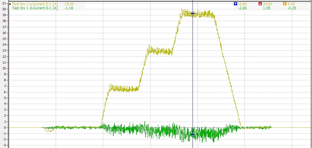
In the image you can see an example of what I described running at 1000rpm (with an external motor) and putting torque steps and the current noise ripple is in the order of 30 Amps (the currents plotted are divided by 10). If I go to higher speeds it gets even worse (I've managed to see ripples of 70-80 Amps at 8000rpm).
Things to take into account:
- I'm running an MTPA algorithm that's why the d current goes slightly negative as the torque increaeses (but the problem is exactly the same even if I remove the algorithm and just apply Id=0)
- Motor characteristics: PMSM, 10 000 rpm, 650 Apeak, 450 Nm, Rs = 7.5mOhm measured (but when estimated it goes to 0.2 Ohm), L = 150 uH, also the estimated flux is about 0.67 which is smaller than what it should be ~0.8
- I'm using a 2 pole pair resolver with a resolver to encoder chip to feed the position to the uC (TMS 320F28069)
- I'm reading the currents using hall effect sensors on the motor phases and they are located so that positive current enters the inverter. I know it should be the other way around so I had to do:
pAdcData->I.value[0] = -value; when I read the currents.
- Since the motor nominal current is higher than 128A I had to apply the trick of changing the currents from A->kA in order not to overflow the IQmath.
- At the moment I'm running sensored and torque control mode so I know I don't really need Instaspin for it but the idea is to run it in speed control at some later stage.
- The PID parameters used are the calculated by the software from the motor parameters but it doesn't seem to make much difference if I try to tweak them manually.
- The deadband values that I'm using are:
#define HAL_PWM_DBFED_CNT (uint16_t)(3.0 * (float_t)USER_SYSTEM_FREQ_MHz) // 3 usec
#define HAL_PWM_DBRED_CNT (uint16_t)(3.0 * (float_t)USER_SYSTEM_FREQ_MHz) // 3 usec
which might be a bit high. I'm not sure of the effect of reducing/increasing those values in the Id/Iq currents.
- I tried to run it sensorless as well and it works but the current ripple looks just as bad as the sensored case.
- Switching frequency of 14kHz.
- I've managed to run the motor at 4-5 krpm up to pretty much full torque (650Apeak) even with those noisy signals but at higher speeds it gets much worse and even increasing the PID gains don't help much.
- I'm using overmodulation, so : #define USER_MAX_VS_MAG_PU (1.3333)
I know it's probably a tricky case but any idea or suggestion would be very much welcomed. Thanks.
Javier


