This thread has been locked.

If you have a related question, please click the "Ask a related question" button in the top right corner. The newly created question will be automatically linked to this question.

CCS/TMS320F28027: Trouble getting ADC result to send through SCI using Simulink.

Part Number: TMS320F28027

Tool/software: Code Composer Studio

Hello, 

This is what I'm working with at the moment: 

  • TMS320F28027 C2000 Launchpad
  • CCS6 with the appropriate support packages installed
  • Matlab w/ Simulink 2016a

I can communicate to and from the launchpad without issue, till now. I am trying to understand and control the ADC and have created a couple of simple Simulink programs to test it. My problem is that I'm able to control the ADC but I cannot get the values from the ADCRESULT register to send through the SCI to a terminal to verify them. One program simply sends a value every 5 seconds, and I'm able to see the "[" header and "]" terminator I'm using to define the result for now, but there is nothing in between them. I though that maybe the ADC wasn't working, but if I go into CCS and watch the ADCRESULT register I'm able to see the value changing appropriately when I apply voltage to the input pins. I'm unsure of what I'm doing wrong and other posts in the forum haven't really answered the similar issue. Could anyone possibly shed some light on this for me? Thank you. 

  • Ian,

    Right now we know you have a problem transmitting, but we dont know where in the chain this problem is located. If my understanding is correct your system's data flow is have something like the below: 

    Voltage source---ADC---SCI---Matlab terminal

    Voltage source->ADC:

    it sounds like you can see values in the ADC's registers so this connection looks OK.

    ADC->SCI:

    it doesn't sound to me like you have checked that the values are correctly copied from the ADC's registers to the SCI's transmit register. Check that the values are correctly transferred!

    SCI->Matlab Terminal:

    you are getting some data, but some is missing. A problem here is possible, but its not the *most* likely place for an issue because we see some data.

    One thing that might help you: Try sending a literal value instead of an ADC Result.

    Hope it helps!

    Regards,
    Cody

  • Hello Cody,

    Thank you for the information. You are correct in assuming the structure of Voltage Source ---ADC---SCI---Putty.

    I didn't think to look at the SCI registers. After checking there, I did find that the ADC values are not being copied to the SCI register. I tried changing settings in the model parameter settings, in the ADC block, and in the SCI block, but I'm not able to get the values to copy over. I also did try sending a simple value through the SCI like you suggested but I still don't get anything in the output.

    One other forum I was reading last night spoke about certain registers being read only and that the EALLOW command could be used to get around that. Would this be part of the issue that's causing my SCI registers not to receive any data?

    I was hoping to use Simulink to quickly program and verify my project, but if I can't get these blocks to do what I want I may just have to revert to coding within CCS.

    Thanks again,
    Ian
  • Ian, did you try contacting MathWorks Technical support?
    www.mathworks.com/.../
  • Ian,

        Have you solved this issue? EALLOW doesn't affect all registers you can find a descrption in the System Control and Interrupts Guide section 5.2. EALLOW is simply a bit in memory that when cleared does not allow some registers to be written, it does not affect reads. This is a security feature, when debugging code it can be helpful to always enable EALLOW, of course in actual application code it is highly recommend to disable it.

    Regards,
    Cody

  • Hello Cody,

    No. I haven't been able to get my original issue solved. I still don't know why I'm unable to get the SCI registers to update when I'm using Simulink. I started to directly modify the TI example SCI program but haven't been able to spend much time on it yet. I think I might need to abandon Simulink for my specific project.

    Thank you for checking in on my problem Cody. I appreciate it.

    Ian
  • Ian,

    Try starting from a ControlSuite example, get it working as desired and see what is different between your code and the example. Be sure to make small incremental changes. A good starting project would be SCI_echoback, scia_loopback, or even scia_loopback_interrupts. If you get any of these projects working with a simple terminal like PuTTY then it should be pretty easy to switch to using Simulink to communicate to the device.

    EDIT: Some of those examples use internal loopback, this internally connects Tx to Rx so anything you send goes directly to the receiver... this can be disabled. SCI Users Guide will detail how to enable this, look at the "SCICCR" register's Loop Back ENA bit.

    Hope it helps!
    Cody

  • I'm not sure how I missed this thread... Can you share the model? Also, do check my video's end part for Simulink example: 

    Regards,

    Gautam

  • Hi Ian,

    I asked my development team for ideas. They ran a quick test and were able to get it to work correctly. They provided some feedback and suggestions - I pasted it below.

    ---

    The problem could be with “PUTTY” tool, as it samples 8bit of data at a time and displays the ASCII equivalent character for the same. Hence when we send the large RAW ADC values, the value gets broken down in to packets of 8bits and each will echoed as its ASCII equivalent. This is not a 1:1 match of what user is getting from ADC block and what he is seeing in putty terminal.


    So user can verify using the Host “Serial Receive” block from “Instrument Control Toolbox” if he has access to the same? Please note: to keep matter simple, I am not using any header/terminator.


    Few suggestions for the user:

    1. Verify the configured baud rate matches with Putty/ Host “Serial Receive” block from “Instrument Control Toolbox”.
    2. Verify the GPIO pin configuration is proper. For me GPIO-28(Rx) and 29(Tx) worked.
    3. Try to work with different option as mentioned above to capture data other than tool like Putty.

    ---

    HTH,

    -Brian

  • Thanks for the input everyone. Gautam, your video made me think about something I could change that might help. And Brian, thanks for asking your team. I have made sure the baud rate matches and verified the GPIO pin, but I am using Putty. I'll try using Hyperterminal or another program and see if that makes a difference.

    I have some free time tonight so I'll get some pictures of my model and the result so everyone knows what I'm seeing on my end.
  • I set up HyperTerminal to receive serial information from the TI. It does show a "value" this time but it's not what I'd expect. As you can see in the picture, there is nothing in the brackets from an input of about 0V to 1V to the ADCIN. Then, from 1V to about 2V there is a white smiley face. 2V or higher gives a black face. This tells me that there is some communication between the ADC and SCI otherwise it wouldn't know what to display when I change the voltage. But it still isn't a value I can use. 

    I am attaching screenshots of the terminal, Simulink, and CCS. I'll let you guys view what I have and add some comments 

    This is the program I have set up in Simulink

    Simulink Settings:

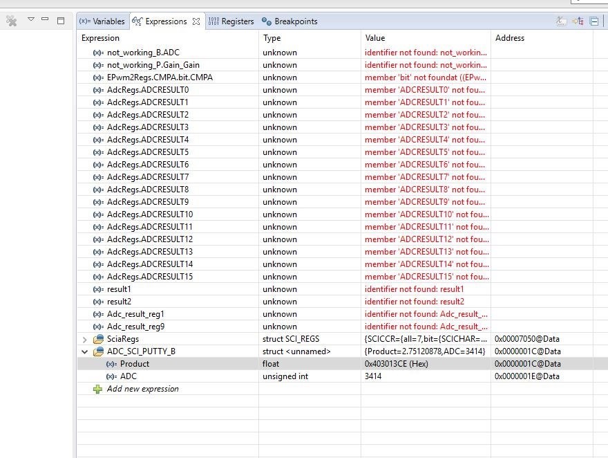
    A screenshot of the registers I'm watching in CCS. I can watch ADCRESULT0 change value when I raise or lower the voltage input, but the SCI registers don't do a thing. 

  • Hi,

    From the model, the output from the product block is a float value which gets stored in memory in its IEEE754 format.

    From the below figure’s, the product value 2.7512(volts) gets stored as 0x403013CE (displayed in hex format in CCS). So, when we use SCI to Transmit 2.7512 volts, it translates to Tx of these individual Hex bytes - (8bits at a time) that are sitting in memory and collectively these bytes are representing the float value of 2.7512. Now when we use a tool like putty or HyperTerminal, these individual hex bytes (8bits at a time) are represented in the ASCII format. It is because of these intermediate representations data does not appear correct.

    The best way to re-construct the original float value of 2.7512 is to write a routine that does the job of packing these bytes together and derive the decimal representation out of it. This can be manually confirmed by looking for the hexadecimal value equivalent to the ASCII character as received on the serial terminal, packing them and use a IEEE754 converter to get the decimal equivalent. A popular tool is available at:

    https://www.h-schmidt.net/FloatConverter/IEEE754.html

    The Serial Receive block in the instrument control toolbox does the same thing.

    HTH

    Regards,

    Venkatesh C

    P.S The SCI regsiter's in your case are holding proper value. SCITXBUF - 0x005D is nothing but ASCII code for terminator symbol ']'.