This thread has been locked.

If you have a related question, please click the "Ask a related question" button in the top right corner. The newly created question will be automatically linked to this question.

DRV8301-69M-KIT: Clarification on DRV8301-69M-KIT EVM's schematic

Part Number: DRV8301-69M-KIT
Other Parts Discussed in Thread: MOTORWARE

Hi,

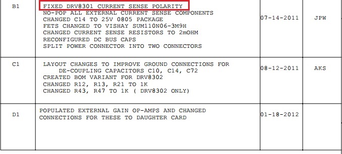
I'm currently designing my own motor controller board based on the DRV8301-69M-KIT evaluation module and looking at the schematic of the module I'd be interested in a clarification on the current sense differential amplifier input polarity. I have attached 3 relevant pictures below from the DRV8301-69M-KIT's schematic showing the current sense connections.

So is the schematic showing correctly that the non-inverting input of the Diff. amp. is to be connected to the ground side of the current shunt?

Just want to get a clarification if the schematic is indeed correct.

  • Yes the schematic is correct. If you simulate it you'll see that the shunt resistor is sensing an inverted current to the real phase current.

    The amplifier circuit inverts this signal again so that you end up with a properly scaled version of the phase current.

  • Now that you mention it like that, yep, makes sense.
    I haven't had a lot of experience with differential sensing before, but I'm learning to do it now. I have mostly done single ended conversions before.
  • The other very important thing to consider is how you sense this signal, you should be triggering the ADC with the PWM and you need to make sure that the low side switch triggers the conversion so that current is flowing through the sense resistor. If this isn't the case when you sense the current you won't actually measure anything!
  • The ADC conversion is triggered by the ePWM module. I'm adapting the lab10a exercise for the DRV8301-69M-KIT EVM from the MotorWare resources to this new controller with the source code where the ADC start of conversion is defined like this:

      //configure the SOCs for drv8301kit_revD
      // sample the first sample twice due to errata sprz342f
      ADC_setSocChanNumber(obj->adcHandle,ADC_SocNumber_0,ADC_SocChanNumber_A6);
      ADC_setSocTrigSrc(obj->adcHandle,ADC_SocNumber_0,ADC_SocTrigSrc_EPWM1_ADCSOCA);
      ADC_setSocSampleDelay(obj->adcHandle,ADC_SocNumber_0,ADC_SocSampleDelay_7_cycles);
    
      ADC_setSocChanNumber(obj->adcHandle,ADC_SocNumber_1,ADC_SocChanNumber_A6);
      ADC_setSocTrigSrc(obj->adcHandle,ADC_SocNumber_1,ADC_SocTrigSrc_EPWM1_ADCSOCA);
      ADC_setSocSampleDelay(obj->adcHandle,ADC_SocNumber_1,ADC_SocSampleDelay_7_cycles);
    
      ADC_setSocChanNumber(obj->adcHandle,ADC_SocNumber_2,ADC_SocChanNumber_B6);
      ADC_setSocTrigSrc(obj->adcHandle,ADC_SocNumber_2,ADC_SocTrigSrc_EPWM1_ADCSOCA);
      ADC_setSocSampleDelay(obj->adcHandle,ADC_SocNumber_2,ADC_SocSampleDelay_7_cycles);

    I'll just remap the ADC pins to the proper SocNumbers and it should run without larger problems.