Other Parts Discussed in Thread: CONTROLSUITE, C2000WARE
Tool/software: Code Composer Studio
Hallo,
is it possilbe to creat two PWM signals using HRPWM for the period and the duty cycle and use a fix deadband?
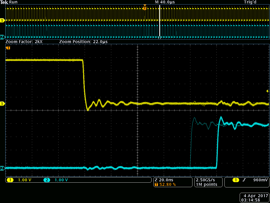
I want do create EPWMxA with a specific period and duty cycle and EPWMxB should be the inverted signal of A with the same deadband. I modified the hrpwm_prdupdown_sfo_cpu01 Project from the controlSUITE examples. But there is always a jitter on channel B.
How can i avoid the jitter?
    //
    // ePWM channel register configuration with HRPWM
    // ePWMxA toggle low/high with MEP control on Rising edge
    //
    EALLOW;
    CpuSysRegs.PCLKCR0.bit.TBCLKSYNC = 0;   // Disable TBCLK within the EPWM
    EDIS;


        EPwm2Regs.TBCTL.bit.PRDLD = TB_SHADOW;  // set Shadow load
        EPwm2Regs.TBPRD = period;               // PWM frequency = 1/(2*TBPRD)
        EPwm2Regs.CMPA.bit.CMPA = period / 2;   // set duty 50% initially
        EPwm2Regs.CMPA.bit.CMPAHR = (1 << 8);   // initialize HRPWM extension
        EPwm2Regs.CMPB.bit.CMPB = period / 2;   // set duty 50% initially
        EPwm2Regs.CMPB.all |= 1;
        EPwm2Regs.TBPHS.all = 0;
        EPwm2Regs.TBCTR = 0;

        EPwm2Regs.TBCTL.bit.CTRMODE = TB_COUNT_UPDOWN; // Select up-down
                                                        // count mode
        EPwm2Regs.TBCTL.bit.SYNCOSEL = TB_SYNC_DISABLE;
        EPwm2Regs.TBCTL.bit.HSPCLKDIV = TB_DIV1;
        EPwm2Regs.TBCTL.bit.CLKDIV = TB_DIV1;          // TBCLK = SYSCLKOUT
        EPwm2Regs.TBCTL.bit.FREE_SOFT = 11;

        EPwm2Regs.CMPCTL.bit.LOADAMODE = CC_CTR_ZERO_PRD;  // LOAD CMPA on CTR = 0
        EPwm2Regs.CMPCTL.bit.LOADBMODE = CC_CTR_ZERO_PRD;
        EPwm2Regs.CMPCTL.bit.SHDWAMODE = CC_SHADOW;
        EPwm2Regs.CMPCTL.bit.SHDWBMODE = CC_SHADOW;

        EPwm2Regs.AQCTLA.bit.CAU = AQ_SET;             // PWM toggle high/low
        EPwm2Regs.AQCTLA.bit.CAD = AQ_CLEAR;
        EPwm2Regs.AQCTLB.bit.CBU = AQ_SET;             // PWM toggle high/low
        EPwm2Regs.AQCTLB.bit.CBD = AQ_CLEAR;

        EALLOW;
        EPwm2Regs.HRCNFG.all = 0x0;
        EPwm2Regs.HRCNFG.bit.EDGMODE = HR_BEP;          // MEP control on
                                                         // both edges.
        EPwm2Regs.HRCNFG.bit.CTLMODE = HR_CMP;          // CMPAHR and TBPRDHR
  //changed                                                       // HR control.
        EPwm2Regs.HRCNFG.bit.HRLOAD = HR_CTR_ZERO_PRD;  // load on CTR = 0
                                                         // and CTR = TBPRD
        EPwm2Regs.HRCNFG.bit.EDGMODEB = HR_BEP;         // MEP control on
                                                         // both edges
        EPwm2Regs.HRCNFG.bit.CTLMODEB = HR_CMP;         // CMPBHR and TBPRDHR
                                                         // HR control
        EPwm2Regs.HRCNFG.bit.HRLOADB = HR_CTR_ZERO_PRD; // load on CTR = 0
                                                         // and CTR = TBPRD
        EPwm2Regs.HRCNFG.bit.AUTOCONV = 1;        // Enable autoconversion for
                                                   // HR period

        EPwm2Regs.HRPCTL.bit.TBPHSHRLOADE = 1;    // Enable TBPHSHR sync
                                                   // (required for updwn
                                                   //  count HR control)
        EPwm2Regs.HRPCTL.bit.HRPE = 1;            // Turn on high-resolution
                                                   // period control.

        CpuSysRegs.PCLKCR0.bit.TBCLKSYNC = 1;      // Enable TBCLK within
                                                   // the EPWM
        EPwm2Regs.TBCTL.bit.SWFSYNC = 1;          // Synchronize high
                                                   // resolution phase to
                                                   // start HR period
        EDIS;


        // ohne EPwm2Regs.DBCTL.bit.POLSEL EPwm2Regs.DBRED EPwm2Regs.DBFED PWM2A = PWM2B
        // Setzen der Totzeit
        // Active Low complementary PWMs - setup the deadband

        EPwm2Regs.DBCTL.bit.OUT_MODE = DB_FULL_ENABLE; // rising edge delay and falling edge delay enabled
        EPwm2Regs.DBCTL.bit.POLSEL = DB_ACTV_HIC;      // Polarity select Control EPWMxB is inverted || 10: Active high complementary (AHC). EPWMxB is inverted.
        EPwm2Regs.DBCTL.bit.IN_MODE = DBA_ALL;         // Dead-Band Input Mode Control: EPWMxA is source for rising and falling edge
        EPwm2Regs.DBRED = EPWM2_DB;                    // rising edge delay value
        EPwm2Regs.DBFED = EPWM2_DB;                    // falling edge delay value