A related question is a question created from another question. When the related question is created, it will be automatically linked to the original question.
If you have a related question, please click the "Ask a related question" button in the top right corner. The newly created question will be automatically linked to this question.
CCS/TMDSDOCK28379D: Connection to the F28379D Delfino Experimenter Kit
I am using F28379D Delfino Experimenter Kit (TMDSDOCK28379D) and have a trouble to start with. Is it possible to connect to the processor via CCS / and through USB connector in docking station? Where can I find a simple video explaining this experimenter kit?
Hi Adam,
I was checking that document but couldn't understand that can I connect to the Dockstation USB port or not. In addition, do I need to change any jumper setting on the Conrolcard or default setting enabling for connecition via dockstation USB port?
I guess this controlcard shall be working with CCS 7.?
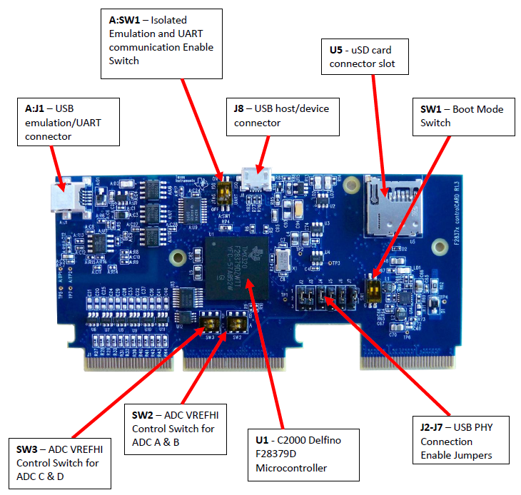
In order to access the controlCARD pins (180 pins), you need to put all J2-J7 jumpers down, so the MCU will connect to 180 pins on the controlCARD docking station.
In order to program your kit with CCS or Simulink, you need to put "A:SW1" ON(up)-ON(up) and "SW1" OFF(up)-ON(down):
Thanks for the nice tips. When I connect to the USB port in Docking station with the setting you mentioned, here is the report when I test the connection with testing (I configure the device with XDS100V2 USB port):
[Start: Texas Instruments XDS100v2 USB Debug Probe_0]
-----[Print the reset-command software log-file]-----------------------------
This utility has selected a 100- or 510-class product. This utility will load the adapter 'jioserdesusb.dll'.
An error occurred while soft opening the controller.
-----[An error has occurred and this utility has aborted]--------------------
This error is generated by TI's USCIF driver or utilities.
The value is '-151' (0xffffff69). The title is 'SC_ERR_FTDI_OPEN'.
The explanation is: One of the FTDI driver functions used during the connect returned bad status or an error. The cause may be one or more of: no XDS100 is plugged in, invalid XDS100 serial number, blank XDS100 EEPROM, missing FTDI drivers, faulty USB cable. Use the xds100serial command-line utility in the 'common/uscif' folder to verify the XDS100 can be located.
[End: Texas Instruments XDS100v2 USB Debug Probe_0]
It seems your error was caused by the FTDI serial port mismatch. Check this to make sure the port number has not been modified by your PC and ensure the port number on PC match that in your configuration file. Usually it is COM 5 or COM 2 or others possibly.
Here is what I found in a Multiday workshop materials:
Initial Hardware Set Up Insert the F28377D controlCARD into the Docking Station connector slot. Using the two (2) supplied USB cables – plug the USB Standard Type A connectors into the computer USB ports and plug the USB Mini-B connectors as follows: • A:J1 on the controlCARD (left side) – isolated XDS100v2 JTAG emulation • J17 on the Docking Station – board power On the Docking Station move switch S1 to the “USB-ON” position. This will power the Docking Station and controlCARD using the power supplied by the computer USB port. Additionally, the other computer USB port will power the on-board isolated JTAG emulator and provide the JTAG communication link between the device and Code Composer Studio.
Saied,
That's correct. you need to have a USB cable connected to J17 (or 5v connected to J1 on the Docking Station) to power up the board and another USB cable connected to A:J1 to power up the JTAG emulator to program the board. you can also use S1 on the Docking Station to toggle to choose USB or 5v external power.
In order to use the 180 pins on the Docking Station, you need to put all J2,J3,J4,J5,J6 and J7 jumpers down.
In order to run your program on the board using CCS or Simulink, put A:SW1 Up-Up (left top side) and SW1 Up-Down (right bottom side).
In order to boot and run your program from the on-board flash, put A:SW1 Down-Up (left top side) and SW1 Up-Up (right bottom side).