This thread has been locked.

If you have a related question, please click the "Ask a related question" button in the top right corner. The newly created question will be automatically linked to this question.

TMS320F28379D: F2837xD Delfino ADC

Part Number: TMS320F28379D

Hi all,

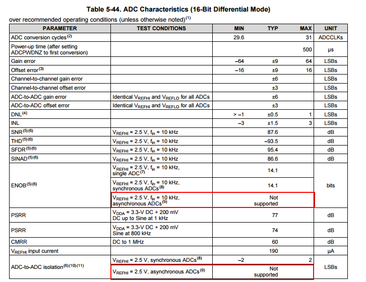
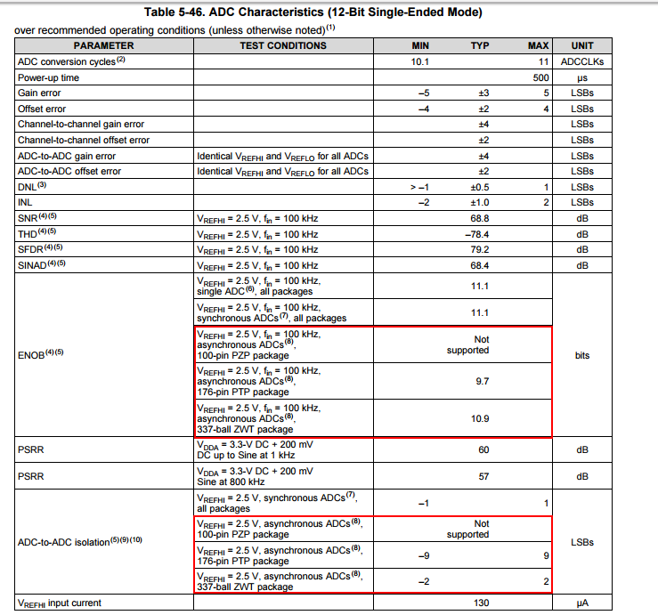
We are working on the F28379D Delfino part 337 ball grid. The requirement is to sample 3 phase voltages and currents with simultaneous V/I pairs in 16 bit mode. I am a bit confused about the 4 ADC modules in the Delfino so please confirm if this scheme works as expected. The trigger source is timer0 for all SOCs. SOC0 should trigger sampling for Va and Ia simultanesouly, SOC1 Vb, Ib and SOC2 Vc and Ic.


                           Differential Inputs        Module          SOC

                Va         C2, C3                     C               0

                Ia         D0, D1                     D               0

                Vb         C4, C5                     C               1

                Ib         D2, D3                     D               1             

                Vc         B4, B5                     B               2

                Ic         D4, D5                     D               2 <- last conversion

Also, in the spruhm8f there is a mention of SOCC and SOCD, is it a typo?

Thanks in advance

  • Hi ED,

    The SOC number won't determine the order of sampling. For each ADC module the sampling will begin immediately if a trigger is received, with the SOC number only determining priority of conversions.

    You can use SOC0 on each of the 4 ADCs to get the first 4 samples simultaneously, and then use SOC1 on two of the ADCs to get the remaining 2 samples. If you also have other trigger sources, it may be a good idea to configure dummy conversions for SOC1 for the two ADCs not already being used to ensure that the ADCs operate synchronously at all times.
  • Thanks Devin,

    I had stated all SOCs were triggered by timer0 and nothing else, in which case the SOC number does have some priority (order), right? If I use SOC0 for the first pair Va/Ia, SOC1 for Vb/Ib and SOC2 for Vc/Ic, would that work in that order (again only single source trigger Timer0)?

  • Hi ED,

    So as configured in your above scenario, when timer 0 trigger occurs, the first set of conversions would be:

    ADCC SOC0 (C2/C3 = Va) in parallel with ADCD SOC0 (D0/D1 = Ia) in parallel with ADCB SOC2 (B4/B5 = Vc)

    Then the next set of conversions would be

    ADCC SOC1 (C4/C5 = Vb) in parallel with ADCD SOC1 (D3/D4 = Ib)

    Then the next set would be

    ADCD SOC2 (D4/D5 = Ic)

    Basically each ADC has its own set of SOCs and operates independently to determine what the next conversion will be. In fact, the ADCs truly operate independently, so if you don't configure the S+H duration to be the same for samples that are occurring in parallel, one ADC will start its next conversion before the others, which can lead to performance issues (see the TRM section about ensuring simultaneous samples).
  • Thanks again for the clarification!
    In other words, the above intended goal of synchronizing conversions of Voltages and Currents in pair for 3 phases cannot be accomplished using 3 ADC modules. It can only be done using 2 modules as shown below? Unfortunately B1 must be saved for DAC purposes so all 3 modules B, C and D are needed in my application.


    Differential Inputs Module SOC

    Va B0, B1 B 0

    Ia D0, D1 D 0

    Vb B2, B3 B 1

    Ib D2, D3 D 1

    Vc B4, B5 B 2

    Ic D4, D5 D 2
  • Hi ED,

    You should also be able to use ADC A. It should definitely be possible to convert 3 pairs of conversions while using all the DAC channels.

    e.g. sample group 1 = A2/A3 || B2/B3 || C2/C3 || D0/D1 then sample group 2 = A4/A5 || B4/B5

    If you don't want to use ADCA , you could get them in 3 rounds using dummy conversions to hold the timing slots, which might look something like:

    B2/B3 || C8/C9 || D2/D3 then B8/B9 || C4/C5 || D4/D5 then B4/B5 || C8/C9 || D0/D1
  • Actually, if you just want to use ADCB and ADD, you could do:

    B2/B3 || D0/D1 then B4/B5 || D2/D3 then B14/B15 || D4/D5
  • Sorry I forgot to mention ADCA is used for something else (DACA, DACB and some other 12-bit signals) so we don't have that. The B14/B15 solution sounds interesting. I will look into that. This has been a very good exercise on the ADC. Thanks for your help!

  • Hi ED,

    Have you looked at the section in the TRM on how to maintain synchronous sampling? We wouldn't recommend running ADCA on its own asynchronous to the other ADCCs, especially if you are using 16-bit mode for some of the ADCs. Instead, you can (manually) switch the resolution between groups of conversions on the same ADC.
  • Yes, I've been consulting the TRM for a bit and found it can be quite confusing at times, like the mention of SOCC and SOCD that might be a typo.

    We intend to use ADCA at 12 bit independently and asynchronously from the other 3 modules (16 bit), probably with another trigger source. This is to read other sensors aside from the 3 phase Vs and Is. Some channels on ADCA might be software SOC force type as well. The TRM states that mixing the resolutions might result in asynchronous operation but on the ADCA that is what we might intend to do for all channels. Do you see any downsides to this setup?

  • Hi Ed,

    I filed a ticket to correct the TRM references to SOCC and SOCD. (The ePWM does have compare C and compare D, but these don't map to their own independent SOC triggers.)

    If you use ADCA independently from the 16-bit ADCs, then the 16-bit ADCs may operate asynchronously to the 12-bit ADCs. This will affect the performance of both the 16-bit and the 12-bit ADCs, but the effect will be much more noticeable in the 16-bit ADCs. We actually explicitly don't support this mode of operation, because the performance will be quite bad.

    You can use all 12-bit inputs on ADCA, but you will need to ensure that they don't overlap with the conversions on the other ADCs.

    An easier solution would be to mix the resolutions in the ADCs and have the 12-bit conversions all occur at a defined time. There are a couple ways you can accomplish this, but the easiest is probably to change the resolution in the ISR for the 16-bit results, and then to change the resolution back in the ISR for the 12-bit results.
  • Hi Devin,

    By bad did you mean out of phase bad or actual signal distortion? Do the ADC modules run totally independently from each other with different trigger sources, especially when overlapping might occur? I had actually considered the solution you suggested (changing resolution on the fly) but thought I wouldn't need it if I dedicated a whole module with a separate trigger for these 12 bit purposes. Distortion might be a deal breaker but out of sync is not a problem for our intended usage.

  • Hi ED,

    The performance will degrade.  For 16-bit, the performance degradation is pretty bad, so we don't suggest/support this mode.  For 12-bit, we specify what the performance degradation will be for ENOB and ADC-to-ADC isolation (basically internal ADC-to-ADC cross-talk):

    You can read more about what does/doesn't qualify as asynchronous in the TRM in the section titled "Ensuring Synchronous Operation", but the short description is that you want to operate all the ADCs in lock-step...so for a given ADC use the same resolution and signal mode configurations and for each SOC use the same trigger sources and same S+H duration (different channel selects are OK).  

    There is no waiting time required between changing the ADC resolution and sampling again.  The preferred way to do this is by using the ADC setMode function.  If this takes too long, you can also just flip the bits for resolution and signal mode...in this case use the function to set the mode to 16-bit to load the correct trims...there will be a slight performance degradation in 12-bit mode due to not loading 12-bit specific trims, but this is not a significant performance hit. 

  • Glad to have this discussion. We would overlook the ADC cross talk otherwise. Though I could see this to be a significant source of bugs for a more demanding and complex sampling scheme where a mixture of 12-bit and 16-bit conversions is required. For us we would just flip the bits in the ISRs and be done with it. I would assume doing it for each of the 4 modules every time an ADC ISR is done, like:

    In 16-bit ISR

    interrupt void ADCB1_ISR(void)                                   // 16-bit ADC

    {

    PieCtrlRegs.PIEACK.all = PIEACK_GROUP1; // Must acknowledge the PIE group

    .......

    .......

    // Change to 12 bit res

    AdcSetMode(ADC_ADCA, ADC_RESOLUTION_12BIT, ADC_SIGNALMODE_SINGLE);
    AdcSetMode(ADC_ADCB, ADC_RESOLUTION_12BIT, ADC_SIGNALMODE_SINGLE);
    AdcSetMode(ADC_ADCC, ADC_RESOLUTION_12BIT, ADC_SIGNALMODE_SINGLE);
    AdcSetMode(ADC_ADCD, ADC_RESOLUTION_12BIT, ADC_SIGNALMODE_SINGLE);

    }

    and in 12-bit ADC ISR

    interrupt void ADCA1_ISR(void)                                   // 12-bit ADC

    {

    PieCtrlRegs.PIEACK.all = PIEACK_GROUP1; // Must acknowledge the PIE group

    .......

    .......

    // Change to 16 bit res

    AdcSetMode(ADC_ADCA, ADC_RESOLUTION_16BIT, ADC_SIGNALMODE_SINGLE);
    AdcSetMode(ADC_ADCB, ADC_RESOLUTION_16BIT, ADC_SIGNALMODE_SINGLE);
    AdcSetMode(ADC_ADCC, ADC_RESOLUTION_16BIT, ADC_SIGNALMODE_SINGLE);
    AdcSetMode(ADC_ADCD, ADC_RESOLUTION_16BIT, ADC_SIGNALMODE_SINGLE);

    }

  • Hi Ed,

    Yeah, that is exactly what we recommend.

    You can then use the SOCA ePWM trigger to trigger one set of conversions and a SOCB trigger to do the others with some phase difference, you can use the same trigger source with "burst mode" to alternate between the sampling sets, or you can use the external interrupt tied to a GPIO to software-trigger the second set of conversions inside the ISR of the first set.
  • Hi Devin,

    Was thinking a bit about this scheme... What happens if sampling one of the resolutions is a lot faster than the other, i.e. NOT interleaving (or what you may have referred to as LOCKSTEPPING?)? Let's say the faster 16-bit samples are read in the ISR, then resolution is changed to 12-bit, but the next conversion is still 16-bit before a slower 12-bit sampling is triggered. Would that create a problem for the 16-bit samples being read as 12-bit?

  • Hi Ed,

    You will definitely want to make sure that all samples are complete before switching the resolution.

    There isn't any danger of damaging the device by sampling in the wrong resolution.

    If the sample was supposed to be 16-bit but was triggered while the ADC was in 12-bit mode, the sample should actually be OK, just only in 12-bit resolution and not benefiting from any common-mode noise rejection from differential signaling.

    If the sample was supposed to be in 12-bit mode but was triggered while the ADC is in 16-bit mode then the sample will likely be corrupt because the ADC will sample a differential pair of signals that are unrelated and not really a differential signal pair.
  • This is not good news at all. Like I said we intend to use the 12-bit module ADCA completely independently of the other 3 16-bit modules, which can mean random sampling as well. Per your explanation it is not possible this way. There must be some kind of lockstep or interleaving relationship between ALL the modules for the mixing of resolutions to work properly. If it's true it could be a major weakness of the ADC feature!

  • Hi ED,

    That is accurate; if you are using a mix of resolutions you will want to treat the 4 ADC system as a single ADC that can do 4 conversions in parallel. If you don't have conversions that go in some slots, then you do a dummy conversion. You want to switch the whole system between resolutions all at the same time. This could get ugly if you have multiple asynchronous loops since you need to be sure the ADC is not converting to switch the resolution.

    If you are using only 12-bit resolution, you can operate the ADCs independently/asynchronously on the 176-pin and 337-ball packages with some performance degradation. On the BGA package the performance degradation is pretty minimal.