This thread has been locked.

If you have a related question, please click the "Ask a related question" button in the top right corner. The newly created question will be automatically linked to this question.

TMS320F28027: Digital power output noise come and go by NOP insertion.

Part Number: TMS320F28027

Hello,

Could you please advise about debug technique or issue mechanism ?
Or, is it possible to compare their good & bad disassembly for us ?


Me and my customer is debugging a C2000 power supply. A constant current source.


The symptom is a spiked noise on the current output.


Part#:
TMS320F28027.


We found:
- The output current was converted by the ADC and its reading also had spikes. +-100LSB.
- The phenomenon appears & disappears by changing function start addresses. NOPs were inserted into a C function.
    - Good source + 1 nop = result good.
    - Good source + 2 nop = result good.
    - Good source + 3 nop = result NO GOOD.
    - Good source + 4 nop = result good.
    - NO GOOD source + 1 nop = result good.


Inconclusive:
- Disassembly inspection. Program flow changes in some funcion, but its detail has not concluded. None of clear findings.
- Other CCS ver. Now CCS5.5 = compiler v6.2.0.

  • Hello Hideaki,

    Are you debugging a C2000 kit? If so, which kit. If not, which topology is the power supply?

    Best Regards,
    Adam Dunhoft
  • Adam, I appreciate your reply.

    Board: Not a TI kit. Customer's original board. We have tested the same board. It would be better to check a RAM memory cells,

    but it has not been tried.

    Topology: I will update tomorrow. >>> Edit> Buck.

  • Adam, the supply topology is buck.
  • Adam,
    As you know our point is the troubleshooting, but one of our member asked a common belief.
    Could you please advise to the additional question ?

    >>>
    Generally, is it possible to relate a slide of the function addresses and an ADC reading error ? Do you (patially or fully) agree with the following input ?
    My customer heard someone's experiece like this, although its detail was not clear.
    As long as I heard, the function address changes, its access time changes (without moves between RAM~Flash), "finally ADC error".
    <<<


    I'm sorry for this additional question.
  • Adam,
    I think there is no penalty when a function lays across the 0x40 boundary. Is it correct ?
  • Sirs,

    We held a meeting and had action items. Could you please tell me the followings today. Please.

    Q1.

    I think there is no penalty when a function lays across the 0x40 boundary in flash memory areas. Is it correct ?

    Q2.

    I think all the flash memory addresses have the same access speed. Is it correct ?

  • Can you confirm from the data sheet that the waitstates you are using in the flash wrapper and the clock speed the device is running at is not near the cutoff?

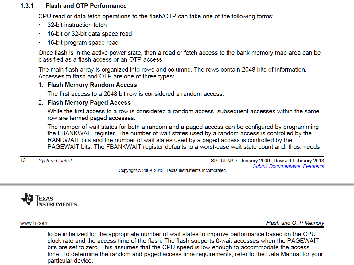
    I do not believe the 0x40 word boundary would be an issue. However, an 0x80 word boundary or 2048 bit boundary could be an issue.

    Below from the Reference Guide  Section 1.3.1 :

    I also suggest using a CPUTimer (perhaps coded in an assembly function) to time code being executed to see if there is a large difference. there is a prefetch or pipeline from the flash bank which acts as an instruction buffer which may be affecting these different results from timings. A CPUTimer would be a good first place to start debugging and get some profiling information.

    sal

  • Sal,
    Thank you for your reply.
    The points are clear on the DS. I'm sorry for your time.

    I will unVerify when we update questions.