Hello,
Each time ADC receives a Start-of-Conversion (SOC) request from ePWMx SOCx trigger to autosequence a series of conversions. I have confused that enabling DELAY() function inside ADC initialisation code, the unwanted PWM pulse was coming. DELAY() function used in ADC to Power UP the ADC Register bit. So, Why unwanted pulse is coming by adding the DELAY() in ADC initialisation code?
Here i'm adding two snapshot picture:
I: Before adding Delay() in AdcRegs. initialisation
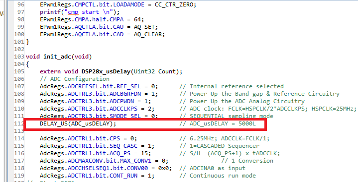
II: After adding Delay() in AdcRegs. initialisation
I: Before adding Delay() in AdcRegs. initialisation

II: After adding Delay() in AdcRegs. initialisation