


Other Parts Discussed in Thread: DRV8305
Hello,
I am working on a firmware for a custom PCB with a TMS320F28069M and DRV8305 based on lab 05b.
This motor driver controls a low-inductance three-phase BLDC. For an aerospace position control application.
The newest version and the PCB flashed the firmware I have so far is able to precisly control the motor at low and high speed and low and high load. However, despite my best efforts, I cannot get the current limiting feature of the speed controller to work. This is a strong requirement for this project.
Here is a description of what seems to be happening:
Whenever the driver reaches the DC current limit set by USER_MOTOR_MAX_CURRENT or is close to reach this limit, It stops responding to speed commands of gMotorVars.SpeedRef_krpm and tries to spin the motor as fast as it can, greatly overshooting the current limit set in user_j1.h. Only a reset of the controller can correct the issue.
Internally, it appears that the IQ current controller reaches its saturation limits because the current feedback is not of the same sign as the current setpoint. Here is a screenshoot of the controller PIDs when the problem happend: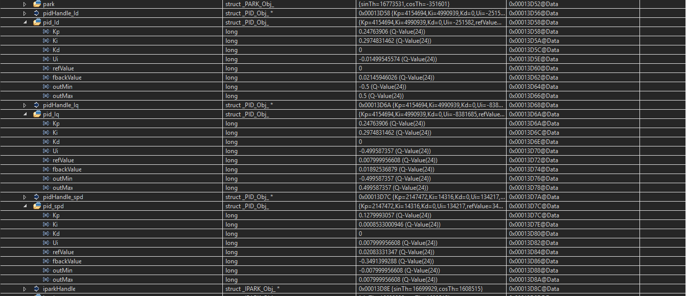
I have no idea what causes this problem but have honestly tried what I could to correct it.
Here are the insteresting sections of my user header:
#define USER_IQ_FULL_SCALE_VOLTAGE_V      (28.0)   // 28.0 Set to Vbus

//! \brief Defines the maximum voltage at the input to the AD converter
//! \brief The value that will be represented by the maximum ADC input (3.3V) and conversion (0FFFh)
//! \brief Hardware dependent, this should be based on the voltage sensing and scaling to the ADC input
#define USER_ADC_FULL_SCALE_VOLTAGE_V       (31.13)  // BOOSTXL-DRV8305EVM = 44.30 V

//! \brief Defines the full scale current for the IQ variables, A
//! \brief All currents are converted into (pu) based on the ratio to this value
//! \brief WARNING: this value MUST be larger than the maximum current readings that you are expecting from the motor or the reading will roll over to 0, creating a control issue
#define USER_IQ_FULL_SCALE_CURRENT_A         (25.0) // BOOSTXL-DRV8305EVM = 24.0 A
//#define USER_IQ_FULL_SCALE_CURRENT_A         (24.0) // BOOSTXL-DRV8305EVM = 24.0 A

//! \brief Defines the maximum current at the AD converter
//! \brief The value that will be represented by the maximum ADC input (3.3V) and conversion (0FFFh)
//! \brief Hardware dependent, this should be based on the current sensing and scaling to the ADC input
#define USER_ADC_FULL_SCALE_CURRENT_A        (33.0)  // BOOSTXL-DRV8305EVM = 47.14 A

//! \brief Defines the number of current sensors used
//! \brief Defined by the hardware capability present
//! \brief May be (2) or (3)
#define USER_NUM_CURRENT_SENSORS            (3)   // 3 Preferred setting for best performance across full speed range, allows for 100% duty cycle

//! \brief Defines the number of voltage (phase) sensors
//! \brief Must be (3)
#define USER_NUM_VOLTAGE_SENSORS            (3) // 3 Required

//! \brief ADC current offsets for A, B, and C phases
//! \brief One-time hardware dependent, though the calibration can be done at run-time as well
//! \brief After initial board calibration these values should be updated for your specific hardware so they are available after compile in the binary to be loaded to the controller
#define   I_A_offset    (0.6584013104)
#define   I_B_offset    (0.6607482433)
#define   I_C_offset    (0.6591419578)

//! \brief ADC voltage offsets for A, B, and C phases
//! \brief One-time hardware dependent, though the calibration can be done at run-time as well
//! \brief After initial board calibration these values should be updated for your specific hardware so they are available after compile in the binary to be loaded to the controller
#define   V_A_offset    (0.4978313446)
#define   V_B_offset    (0.4975547791)
#define   V_C_offset    (0.4955942035)


//! \brief CLOCKS & TIMERS
// **************************************************************************
#define USER_PWM_FREQ_kHz                (30.0) //30.0 Example, 8.0 - 30.0 KHz typical; 45-80 KHz may be required for very low inductance, high speed motors


#define USER_MAX_VS_MAG_PU        (0.5)    // Set to 0.5 if a current reconstruction technique is not used.  Look at the module svgen_current in lab10a-x for more info.

//! \brief DECIMATION
// **************************************************************************
//! \brief Defines the number of pwm clock ticks per isr clock tick
//!        Note: Valid values are 1, 2 or 3 only
#define USER_NUM_PWM_TICKS_PER_ISR_TICK        (1)

//! \brief Defines the number of isr ticks (hardware) per controller clock tick (software)
//! \brief Controller clock tick (CTRL) is the main clock used for all timing in the software
//! \brief Typically the PWM Frequency triggers (can be decimated by the ePWM hardware for less overhead) an ADC SOC
//! \brief ADC SOC triggers an ADC Conversion Done
//! \brief ADC Conversion Done triggers ISR
//! \brief This relates the hardware ISR rate to the software controller rate
//! \brief Typcially want to consider some form of decimation (ePWM hardware, CURRENT or EST) over 16KHz ISR to insure interrupt completes and leaves time for background tasks
#define USER_NUM_ISR_TICKS_PER_CTRL_TICK       (2)      // 2 Example, controller clock rate (CTRL) runs at PWM / 2; ex 30 KHz PWM, 15 KHz control

//! \brief Defines the number of controller clock ticks per current controller clock tick
//! \brief Relationship of controller clock rate to current controller (FOC) rate
#define USER_NUM_CTRL_TICKS_PER_CURRENT_TICK   (1)      // 1 Typical, Forward FOC current controller (Iq/Id/IPARK/SVPWM) runs at same rate as CTRL.

//! \brief Defines the number of controller clock ticks per estimator clock tick
//! \brief Relationship of controller clock rate to estimator (FAST) rate
//! \brief Depends on needed dynamic performance, FAST provides very good results as low as 1 KHz while more dynamic or high speed applications may require up to 15 KHz
#define USER_NUM_CTRL_TICKS_PER_EST_TICK       (1)      // 1 Typical, FAST estimator runs at same rate as CTRL;

//! \brief Defines the number of controller clock ticks per speed controller clock tick
//! \brief Relationship of controller clock rate to speed loop rate
#define USER_NUM_CTRL_TICKS_PER_SPEED_TICK  (15)   // 15 Typical to match PWM, ex: 15KHz PWM, controller, and current loop, 1KHz speed loop

//! \brief Defines the number of controller clock ticks per trajectory clock tick
//! \brief Relationship of controller clock rate to trajectory loop rate
//! \brief Typically the same as the speed rate
#define USER_NUM_CTRL_TICKS_PER_TRAJ_TICK   (15)   // 15 Typical to match PWM, ex: 10KHz controller & current loop, 1KHz speed loop, 1 KHz Trajectory

//! \brief LIMITS
// **************************************************************************
//! \brief Defines the maximum negative current to be applied in Id reference
//! \brief Used in field weakening only, this is a safety setting (e.g. to protect against demagnetization)
//! \brief User must also be aware that overall current magnitude [sqrt(Id^2 + Iq^2)] should be kept below any machine design specifications
#define USER_MAX_NEGATIVE_ID_REF_CURRENT_A     (-0.5 * USER_MOTOR_MAX_CURRENT)   // -0.5 * USER_MOTOR_MAX_CURRENT Example, adjust to meet safety needs of your motor

//! \brief Defines the R/L estimation frequency, Hz
//! \brief User higher values for low inductance motors and lower values for higher inductance
//! \brief motors.  The values can range from 100 to 300 Hz.
#define USER_R_OVER_L_EST_FREQ_Hz (300)               // 300 Default

//! \brief Defines the low speed limit for the flux integrator, pu
//! \brief This is the speed range (CW/CCW) at which the ForceAngle object is active, but only if Enabled
//! \brief Outside of this speed - or if Disabled - the ForcAngle will NEVER be active and the angle is provided by FAST only
#define USER_ZEROSPEEDLIMIT   (0.5 / USER_IQ_FULL_SCALE_FREQ_Hz)     // 0.002 pu, 1-5 Hz typical; Hz = USER_ZEROSPEEDLIMIT * USER_IQ_FULL_SCALE_FREQ_Hz

//! \brief Defines the force angle frequency, Hz
//! \brief Frequency of stator vector rotation used by the ForceAngle object
//! \brief Can be positive or negative
#define USER_FORCE_ANGLE_FREQ_Hz   (2.0 * USER_ZEROSPEEDLIMIT * USER_IQ_FULL_SCALE_FREQ_Hz)      // 1.0 Typical force angle start-up speed

//! \brief POLES
// **************************************************************************
//! \brief Defines the analog voltage filter pole location, Hz
//! \brief Must match the hardware filter for Vph
#define USER_VOLTAGE_FILTER_POLE_Hz  (357.0)   // BOOSTXL-DRV8305 = 344.62 Hz

//! \brief USER MOTOR & ID SETTINGS
// **************************************************************************

//! \brief Define each motor with a unique name and ID number
// BLDC & SMPM motors
#define Estun_EMJ_04APB22           101
#define Anaheim_BLY172S             102
#define Teknic_M2310PLN04K          104

// IPM motors
// If user provides separate Ls-d, Ls-q
// else treat as SPM with user or identified average Ls
#define Belt_Drive_Washer_IPM       201
#define Anaheim_Salient             202

// ACIM motors
#define Marathon_5K33GN2A           301


#define USER_MOTOR Maxon_EC22

#elif (USER_MOTOR == Maxon_EC22)
#define USER_MOTOR_TYPE                 MOTOR_Type_Pm
#define USER_MOTOR_NUM_POLE_PAIRS       (1)
#define USER_MOTOR_Rr                   (NULL)
#define USER_MOTOR_Rs                   (0.43)
#define USER_MOTOR_Ls_d                 (0.00011737140144)
#define USER_MOTOR_Ls_q                 (0.00011737140144)
#define USER_MOTOR_RATED_FLUX           (0.0535185114)
#define USER_MOTOR_MAGNETIZING_CURRENT  (NULL)
#define USER_MOTOR_RES_EST_CURRENT      (0.2)
#define USER_MOTOR_IND_EST_CURRENT      (-0.2)
#define USER_MOTOR_MAX_CURRENT          (0.5)
#define USER_MOTOR_FLUX_EST_FREQ_Hz     (20.0)

Any idea why this is happening? I thought it was a per unit scaling issue at some point but couldn't find anything wrong with my user parameters

Thank you for your help.
-Nicolas de Maubeuge
