Part Number: TMS320F28069M
Other Parts Discussed in Thread: MOTORWARE
Hi TI'ers
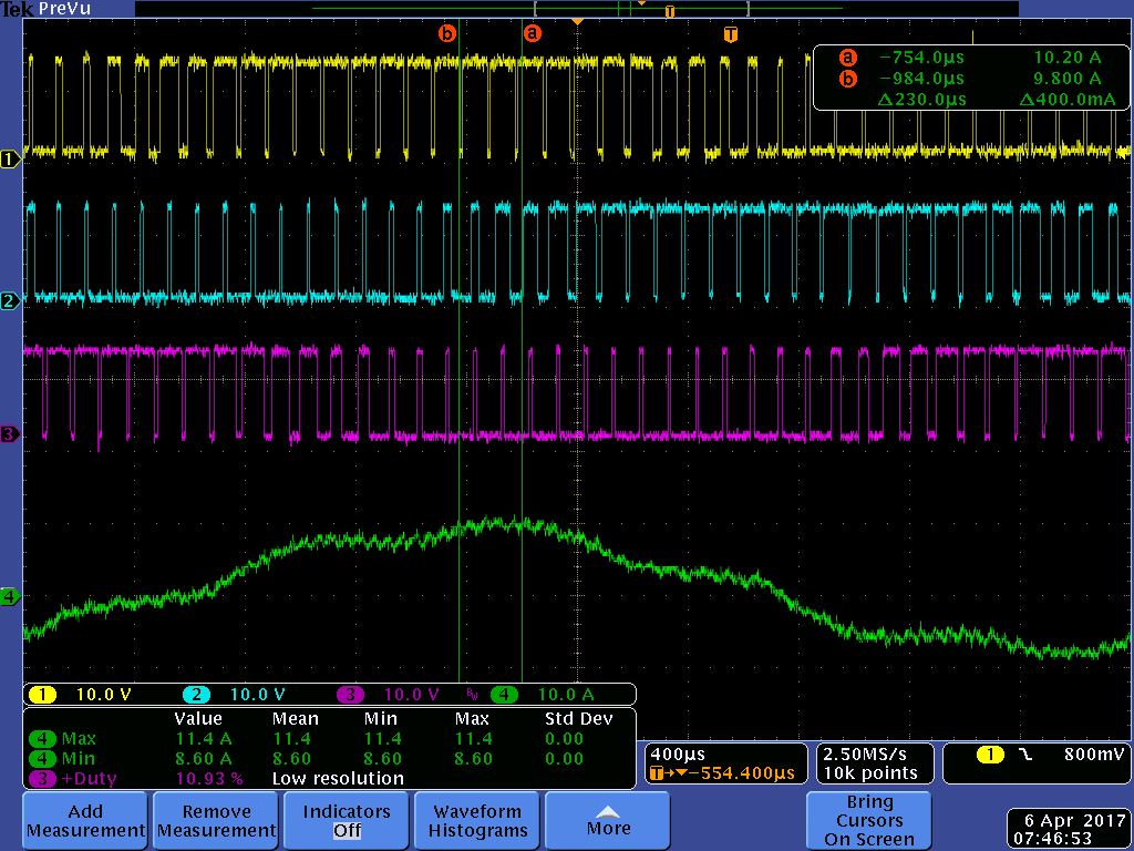
We are having an issue where when running our pumps (mostly identical to the LaunchXL-F28069M + BOOSTXL-DRV8301 EVM) but with 2 pumps per picollo. We are reaching some power limit that we don't understand. Both pumps run at 12V, ~10A peak/peak (8k RPM) when looking at the phase currents (on the wires to the motors). We can run each motor individually OK at that current, but when we run both pumps, we can run one up to that current, but once the 2nd one runs up and hits about +/- 9A,(7000-7500 RPM) the 1st one will lose sync and generate a huge current spike +/- 40A for cycle causing it to stop and restart.
Our requirement is for both to run at 8k RPM. the SW is based on lab 10d. this is the same project you have been helping Louis Zhu with as we running 1 ISR routine. CPU times look good ~160uS / 200uS period for the motor ISR and the main loop takes 1.4mS to complete (not much different than lab10d), so it completes every 6-7 Motor ISRs. Is that OK?.
We have disabled the OTCW detection in order to help troubleshoot this issue. We don't see the DRV generate a FAULT until after this event.
Here's the critical values in the user.xx.h file:
/// motor: 10000 RPM * 4 / 120 = 333.3
#define USER_IQ_FULL_SCALE_FREQ_Hz_M1 (333.3)
// FIX with both ADC and DRV with 2.5V reference ~2x USER_ADC_FULL_SCALE_VOLTAGE
#define USER_IQ_FULL_SCALE_VOLTAGE_V_M1 (40.0)
// FIX with both ADC and DRV with 2.5V reference
// Vin * 4.99 / (4.99 +34.8) = 2.5 ===> vin (max) = 19.93487
#define USER_ADC_FULL_SCALE_VOLTAGE_V_M1 (19.93487)
// FIX with both ADC and DRV with 2.5V reference -- ~ 20% above USER_IQ_FULL_SCALE_CURRENT_A
#define USER_IQ_FULL_SCALE_CURRENT_A_M1 (32.0)
// FIX with both ADC and DRV with 2.5V reference wiht 9milliOhm sense
#define USER_ADC_FULL_SCALE_CURRENT_A_M1 (27.78)
#define USER_NUM_CURRENT_SENSORS_M1 (2) // 2 available on Mentor board
#define USER_NUM_VOLTAGE_SENSORS_M1 (3) // 3 Required
#define V_A_offset_M1 (0.1198145) //
#define V_B_offset_M1 (0.1198781) //
#define V_C_offset_M1 (0.1191706) //
#define USER_PWM_FREQ_kHz_M1 (10.0) //30.0 Example, 8.0 - 30.0 KHz typical; 45-80 KHz may be required for very low inductance, high speed motors
#define USER_MAX_VS_MAG_PU_M1 (0.5) // Set to 0.5 if a current reconstruction technique is not used. Look at the module svgen_current in lab10a-x for more info.
#define USER_NUM_PWM_TICKS_PER_ISR_TICK_M1 (2)
#define USER_NUM_ISR_TICKS_PER_CTRL_TICK_M1 (1) // 2 Example, controller clock rate (CTRL) runs at PWM / 2; ex 30 KHz PWM, 15 KHz control
#define USER_NUM_CTRL_TICKS_PER_CURRENT_TICK_M1 (1) // 1 Typical, Forward FOC current controller (Iq/Id/IPARK/SVPWM) runs at same rate as CTRL.
#define USER_NUM_CTRL_TICKS_PER_EST_TICK_M1 (1) // 1 Typical, FAST estimator runs at same rate as CTRL;
#define USER_NUM_CTRL_TICKS_PER_SPEED_TICK_M1 (15) // 15 Typical to match PWM, ex: 15KHz PWM, controller, and current loop, 1KHz speed loop
#define USER_NUM_CTRL_TICKS_PER_TRAJ_TICK_M1 (15) // 15 Typical to match PWM, ex: 10KHz controller & current loop, 1KHz speed loop, 1 KHz Trajectory
-- --- default values for the others
#define USER_MOTOR_TYPE_M1 MOTOR_Type_Pm // Motor_Type_Pm (All Synchronous: BLDC, PMSM, SMPM, IPM) or Motor_Type_Induction (Asynchronous ACI)
#define USER_MOTOR_NUM_POLE_PAIRS_M1 (2) // PAIRS, not total poles. Used to calculate user RPM from rotor Hz only
#define USER_MOTOR_Rr_M1 (NULL) // Induction motors only, else NULL
#define USER_MOTOR_Rs_M1 (0.04696075) // (0.074250020) // Identified phase to neutral resistance in a Y equivalent circuit (Ohms, float)
#define USER_MOTOR_Ls_d_M1 (0.000127290) // (0.000123519) // For PM, Identified average stator inductance (Henry, float)
#define USER_MOTOR_Ls_q_M1 (0.000127290) // (0.000123519) // For PM, Identified average stator inductance (Henry, float)
#define USER_MOTOR_RATED_FLUX_M1 (0.0150248) // (0.016194884) // Identified TOTAL flux linkage between the rotor and the stator (V/Hz)
#define USER_MOTOR_MAGNETIZING_CURRENT_M1 (NULL) // Induction motors only, else NULL
#define USER_MOTOR_RES_EST_CURRENT_M1 (2.0) // During Motor ID, maximum current (Amperes, float) used for Rs estimation, 10-20% rated current
#define USER_MOTOR_IND_EST_CURRENT_M1 (-2.0) // During Motor ID, maximum current (negative Amperes, float) used for Ls estimation, use just enough to enable rotation
#define USER_MOTOR_MAX_CURRENT_M1 (15.0) // CRITICAL: Used during ID and run-time, sets a limit on the maximum current command output of the provided Speed PI Controller to the Iq controller
#define USER_MOTOR_FLUX_EST_FREQ_Hz_M1 (20.0) // During Motor ID, maximum commanded speed (Hz, float), ~10% rated
my question is are we setting these 3 current parameters correctly for this application?
USER_ADC_FULL_SCALE_CURRENT_A_M1 (27.78) = +13.69A measurement range due to 2.5V reference and 9mOhm sense resistor and 12V Inverter
USER_IQ_FULL_SCALE_CURRENT_A_M1 (32.0) = +/- 16A max values used internally. Cannot roll over. User selected
USER_MOTOR_MAX_CURRENT_M1 (15.0) = rated motor current. User selected per motor
is the USER_MOTOR_MAX_CURRENT_M1 value a peak or RMS value? Is that limiting us?
Should we be setting the IQ_FULL_SCALE... value higher?
It seems we are hitting a power limit, as we can trip this by running slower and increasing the load or either combination - as long as we are ~+/-10A on the phase currents. The 12V bus looks OK - we increased the capacitance to keep it from sagging during these events, thinking it was the cause, but it wasn't.
Here's the waveform at the event...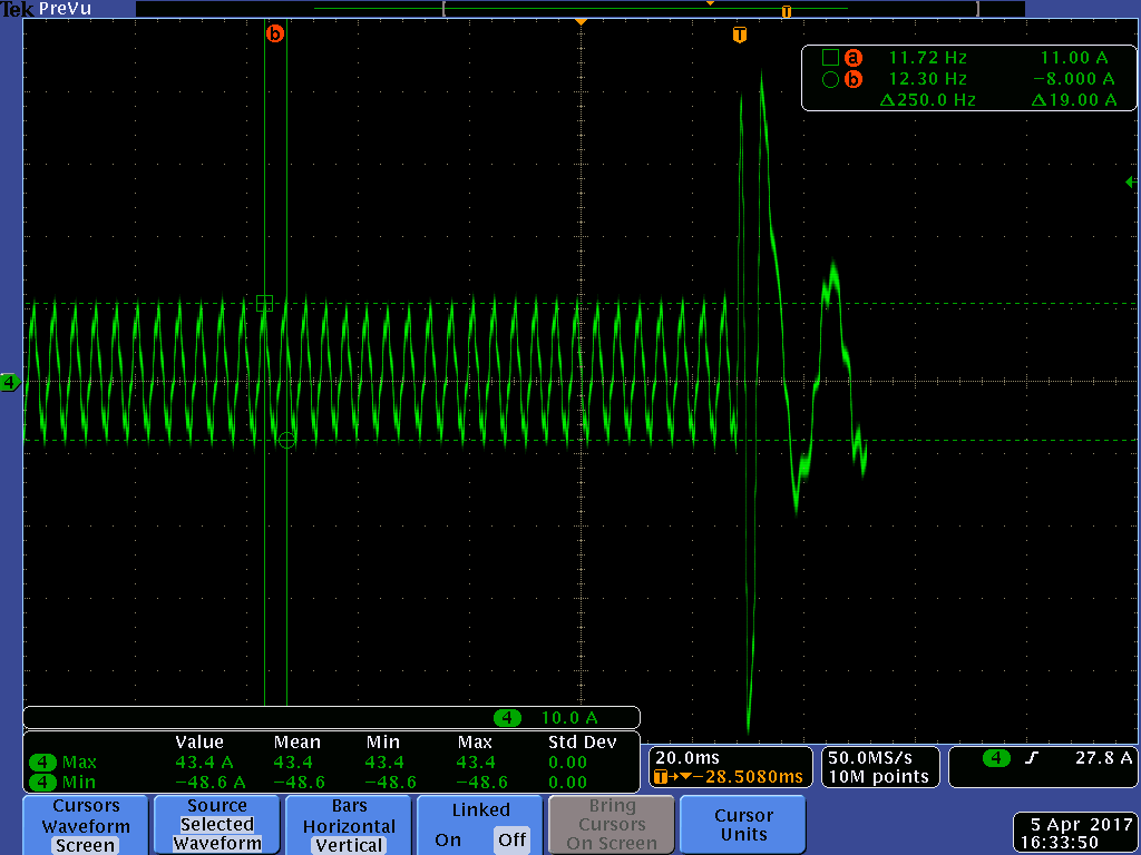
Thanks for any help!
- Robb